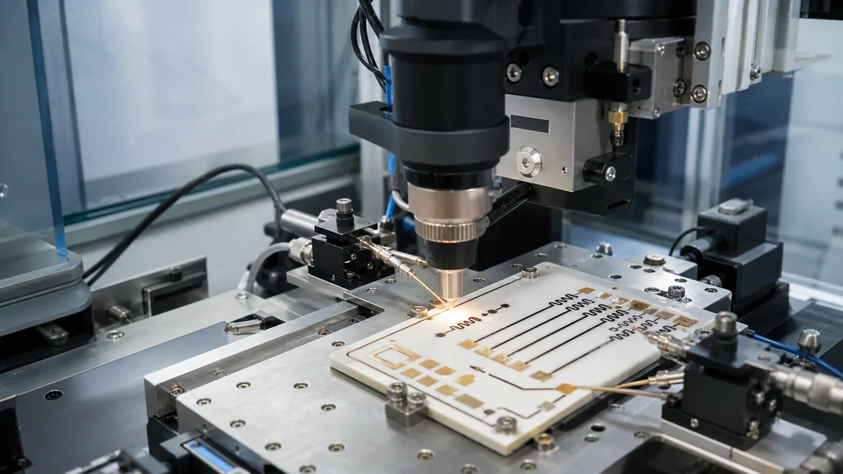
Laser trimming is used to adjust fired thick film resistors to a target resistance or circuit output. It is one of the most important precision steps in custom ceramic thick film circuits, fuel sensor circuits, throttle sensor resistors, and hybrid resistor networks.
Passive trimming
Passive trimming measures the resistor value and cuts the resistor body until the target resistance is reached. This is suitable when the specification is an individual resistor value and tolerance.
Active trimming
Active trimming powers the circuit and trims until a functional output reaches the target. This can be used for sensor output, gain, offset, voltage, frequency, or other system-level parameters.
Trim geometry
Common trim paths include straight cuts, L-cuts, plunge cuts, and serpentine adjustments. The right path depends on resistor geometry, required adjustment range, current distribution, and long-term stability.
Heat affected zone
The laser locally removes resistor material and creates a heat affected zone. Excessive energy, poor focus, or unsuitable trim geometry can cause microcracks, local stress, drift, or increased noise.
Post-trim stability
After trimming, stability should be verified under the actual operating environment. Thermal aging, humidity, power loading, and thermal cycling can reveal drift that a room-temperature resistance check cannot.
RFQ information for trimmed resistors
Provide target value, tolerance, TCR, power, working temperature, substrate material, resistor drawing, trim mode, and final test condition. For active trim, provide the circuit target and measurement method.