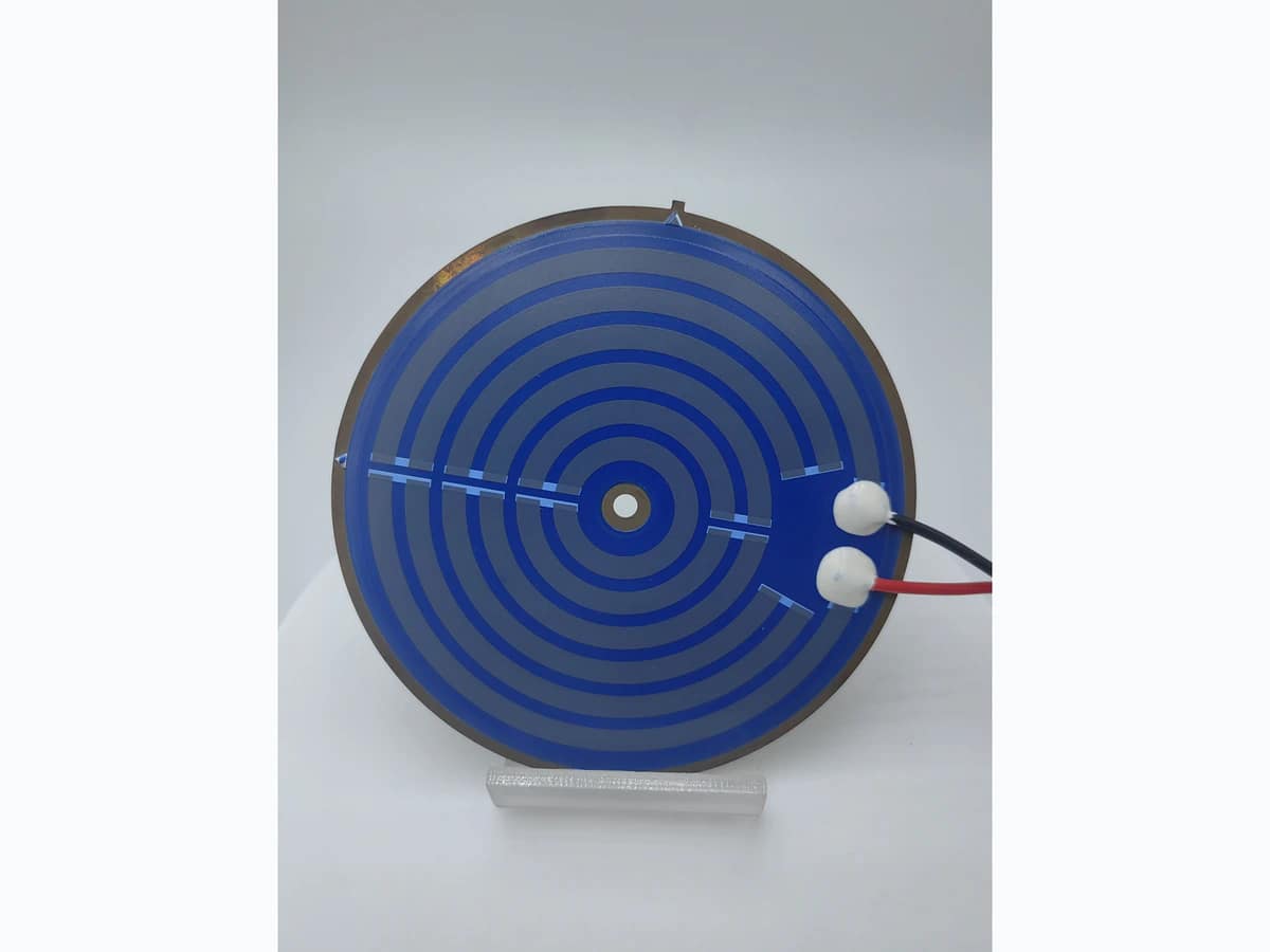
Plate, vessel, and dielectric interface
Review plate material and thickness, diameter and center opening, flatness, vessel contact, joining or clamping, dielectric coverage, edge clearances, grounding, sealing boundary, and assembly stress.

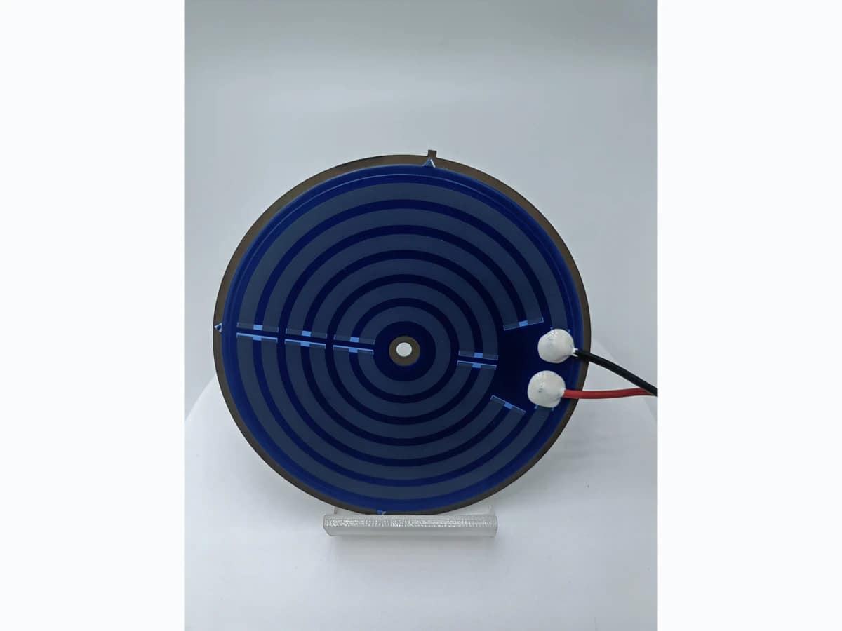
Kettle Heater Engineering
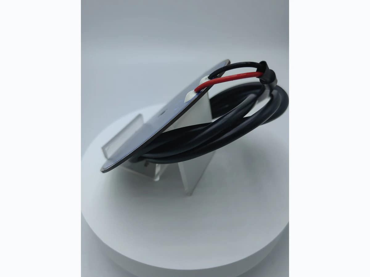
An electric kettle thick film heater must connect the circular heating plate, dielectric and printed resistance system, terminal joints and leads, vessel contact, water-side heat load, controls, dry-fire protection, grounding, and appliance validation. The supplied photographs show two visible circular path layouts on blue surfaces, metal edges, center openings, terminal joints, red and black leads, and a side or rear assembly view. Send the kettle and heater drawings plus the complete electrical and safety conditions for review.
Verified capability review
Electric Kettle Thick Film Heater is shown against approved company capability control sheets.
Capability source: approved company category control sheets. Final values remain drawing- and sample-controlled.
| Parameter | Standard capability | Engineering review range | Final release |
|---|---|---|---|
| Substrate Material | Stainless steel | Alternative approved route selected from heat path, insulation, corrosion, outline, mounting, and process compatibility | Approved material specification, drawing, and incoming criteria |
| Dielectric Layers | 3–4 printed dielectric layers typical | Layer count, fired thickness, edge margin, creepage, clearance, grounding, and interface by safety review | Released insulation stack and agreed IR/withstand test plan |
| Heater Resistor | RuO₂ / Metal-based / PTC | RuO₂, metal-based, or PTC route selected for resistance, temperature coefficient, firing/cure, and duty profile | Released drawing and approved sample |
| Conductor System | Ag / Ag-Pd / Metal terminal | Ag, Ag-Pd, or metal terminal route by current, connection, temperature, corrosion, and assembly | Approved material stack, assembly interface, and sample |
| Rated Voltage | Project-rated after electrical and thermal review | Approved category engineering envelope: 3–240 V AC/DC typical | Approved electrical-thermal design and instrumented prototype validation |
| Rated Power | Project-rated after electrical and thermal review | Approved category engineering envelope: 1–2,000 W typical; heat load and available area are checked | Approved electrical-thermal design and instrumented prototype validation |
| Parameter | Standard capability | Engineering review range | Final release |
|---|---|---|---|
| Target Resistance | Project-rated after electrical and thermal review | Approved category engineering envelope: 0.1 Ω–10 kΩ typical; calculated from released voltage and power | Released electrical limits, measurement method, and approved sample |
| Resistance Tolerance | ±5% typical | ±5% typical; reference temperature, lead compensation, and measurement timing are defined | Released electrical limits, measurement method, and approved sample |
| Power Density | Project-rated after electrical and thermal review | Approved category engineering envelope: 1–60 W/cm² typical; local cooling, duty, contact, and hot spots are reviewed | Approved electrical-thermal design and instrumented prototype validation |
| Operating Temperature | Ceramic/metal route ≤600°C typical | Continuous, peak, ambient, fluid, interface, and no-flow/no-load conditions are separated for validation | Approved electrical-thermal design and instrumented prototype validation |
| Process Temperature | ≈590°C metal-substrate process route | Actual peak, dwell, atmosphere, and refire/cure exposure follow the selected material stack | Approved material-process route and production traveler |
| Electrical Test | IR ≥100 MΩ / Hi-pot ≥1.5 kVAC typical | IR, hi-pot voltage, ramp, dwell, leakage, humidity state, and pre/post conditioning by product safety plan | Released insulation stack and agreed IR/withstand test plan |
| Life-test conditions | On/off cycling is defined with powered dwell, cooling dwell, mounting, cooling medium, and starting temperature | Cycle count, voltage, load, fault conditions, resistance drift, insulation, leakage, and appearance limits by application risk | Agreed endurance profile and pre/post-test acceptance report |
Four controls connect the circular heater plate, printed stack, terminal and lead assembly, kettle vessel, water-side heat load, controls, and appliance validation. Supplied photos support visible layout review; materials, ratings, boil performance, safety results, endurance, and approvals remain project-controlled.
Review plate material and thickness, diameter and center opening, flatness, vessel contact, joining or clamping, dielectric coverage, edge clearances, grounding, sealing boundary, and assembly stress.
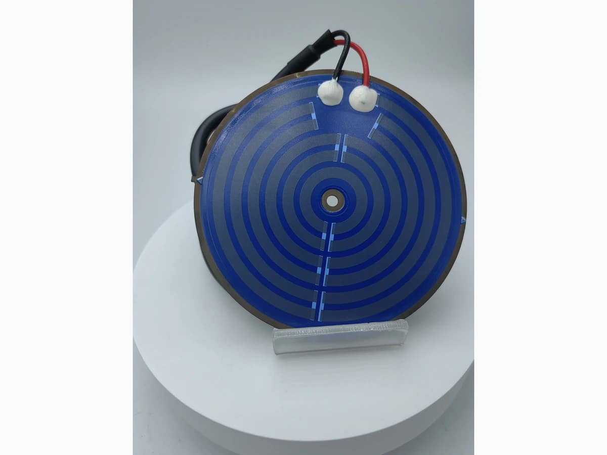
Connect resistance, voltage, power, power density, printed zones, local loading, water volume, heat transfer, boil time, keep-warm duty, sensor and cutoff positions, and dry-fire protection.
Define joint and pad materials, red and black lead specifications, polarity, joining temperature, insulation, routing, strain relief, connector, grounding path, pull criteria, moisture protection, and service assembly.
Release resistance, leakage, insulation, hi-pot, grounding continuity, rated-power, boil, keep-warm, thermal mapping, dry-fire, cycling, endurance, functional, sampling, calibration, and signed-record requirements.
These application illustrations show conditional appliance-heater directions. Suitability depends on the released vessel and plate geometry, water load, rated input, terminal and lead assembly, grounding, controls, dry-fire protection, applicable safety standard, endurance plan, and production tests.
Application images are engineering illustrations, not customer projects, production records, or evidence of a released design. Suitability is confirmed only after the drawing, interfaces, operating conditions, risks, and validation plan are reviewed.
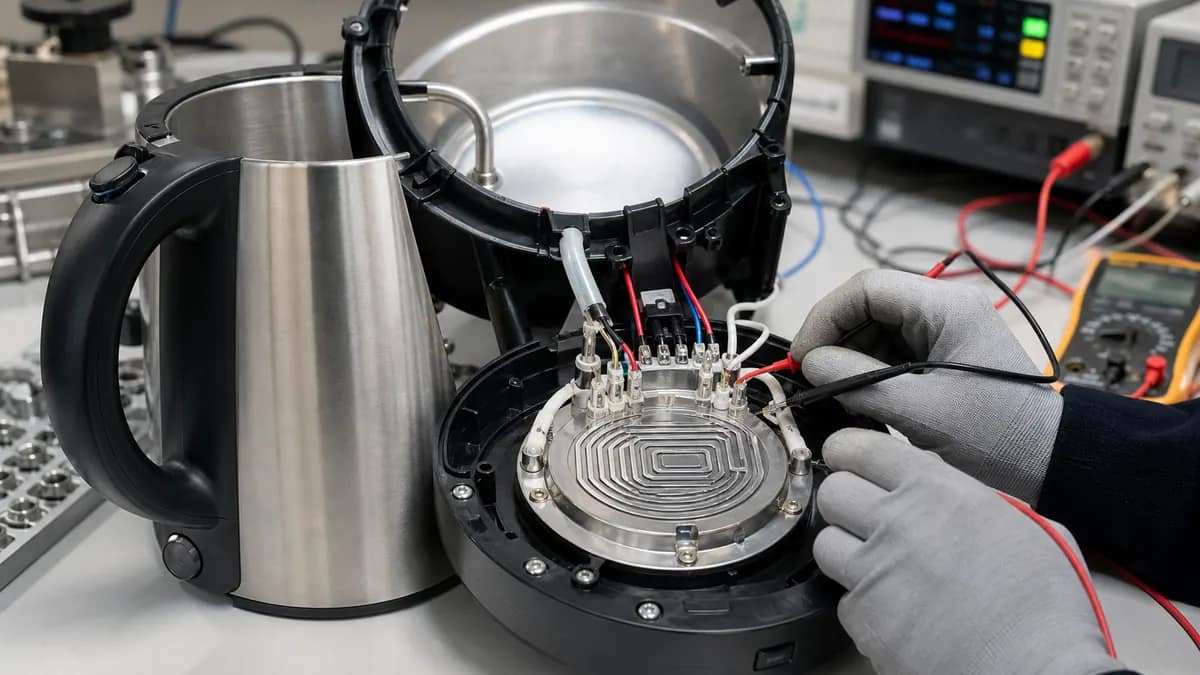 Application illustration
A circular heater plate may support rapid kettle heating after vessel contact, water volume, rated supply and power, boil time, sensor and cutoff logic, grounding, steam and moisture exposure, dry-fire protection, and appliance tests are released.
Review kettle inputs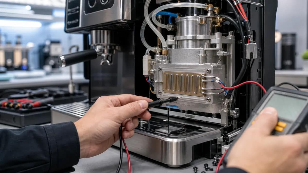 Application illustration
Related metal-base heaters may be reviewed for beverage-water heating when flow or reservoir conditions, scale and cleaning exposure, temperature control, pump or valve interfaces, terminals, grounding, insulation, and appliance validation are defined.
Review beverage inputs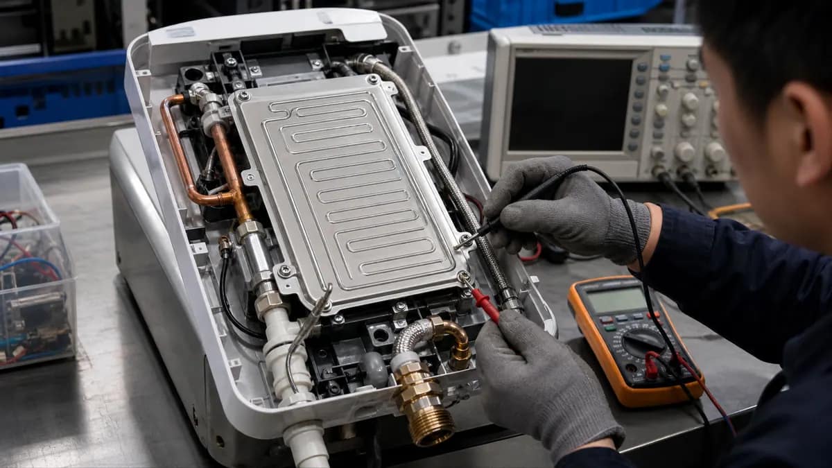 Application illustration
A kettle-style printed plate can be evaluated for other compact water modules after the vessel interface, thermal contact, rated input, hydraulic condition, sensing, over-temperature and dry-run protection, sealing, grounding, and equipment safety are specified.
Review water-module inputsFive supplied photographs visibly confirm circular metal-edged heater plates with blue surface fields, two distinct gray concentric printed-path layouts, center openings, terminal regions covered by white joining material, red and black leads, edge tabs or features, and front, angled, and side or rear views. They do not establish metal or printed material identities, dimensions, resistance, voltage, power, boil performance, insulation, leakage, grounding, dry-fire behavior, endurance, approval, lot, inspection, or shipment status.
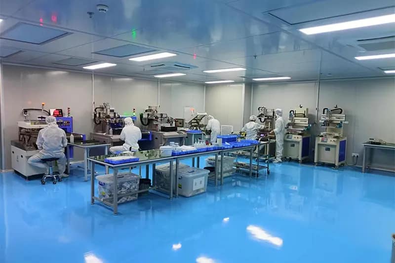
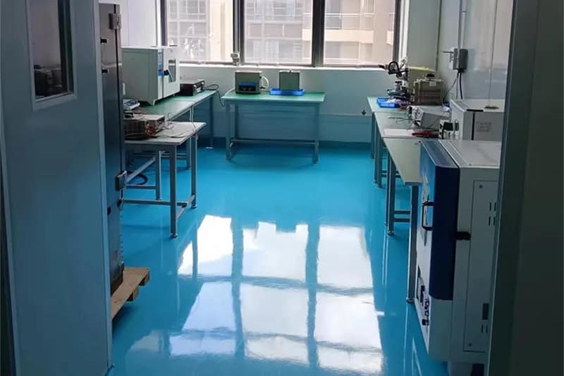
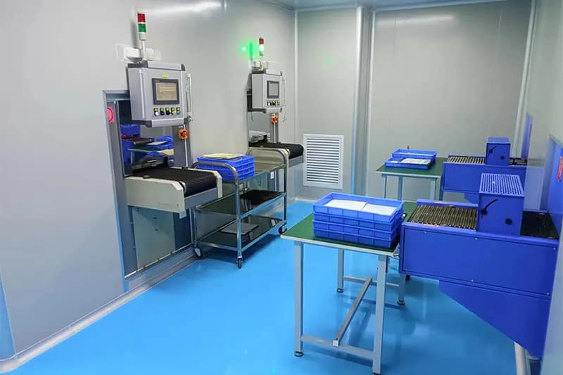
Company resources support controlled thick film printing, thermal processing, laboratory inspection, and managed production in Dongguan.
For kettle heaters, the approved plate and printed stack, terminal and lead assembly, grounding, resistance and safety tests, boil and dry-fire validation, sampling, traceability, and acceptance records are released per project.

Short answers for quotation planning; released drawings and validation requirements remain controlling.
Send the heater and kettle-vessel drawings, plate material and thickness, contact and mounting method, rated voltage and frequency or DC supply, target power and resistance, water volume, boil-time target, keep-warm duty, sensor and thermostat details, dry-fire and over-temperature protection, terminals and leads, grounding, steam and moisture exposure, quantities, applicable safety standard, endurance plan, and acceptance records.
Power cannot be chosen from plate diameter alone. Engineering reviews the supply, water mass and starting temperature, desired heat-up time, vessel efficiency, heat loss, heater contact, printed power density, local hot spots, sensor and cutoff response, steam condition, dry-fire case, control tolerances, and appliance limits. Prototype testing under the released vessel and water load confirms the practical rating.
The plan may include resistance and power, insulation resistance, hi-pot and leakage, grounding continuity, temperature mapping, boil and keep-warm operation, sensor and cutoff response, dry-fire and abnormal operation, moisture and scale exposure, thermal cycling, terminal pull or routing checks, endurance, and final appliance tests. Exact methods and limits follow the customer drawing and applicable product standard.
No. They verify visible circular plate, printed-path, terminal, lead, edge, and profile features only. Material identity, rated input, boil performance, leakage, insulation, grounding, dry-fire protection, endurance, regulatory approval, production lot, inspection, and shipment status require authorized project documentation.
Send the kettle and heater drawings, water-load and rated-input conditions, plate and printed-stack requirements, terminal and lead assembly, grounding, sensors and controls, abnormal-use cases, safety standard, endurance plan, quantities, and required records. Engineering will review the complete appliance interface before confirming the heater route.
PDF, DWG, DXF, STEP, Gerber, ZIP, Excel, Word, or sample photos are accepted.
The drawing-upload form loads as you reach this section.