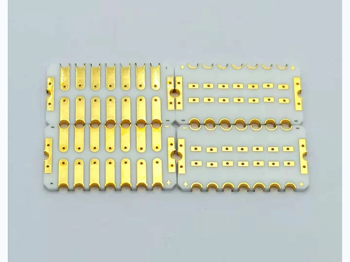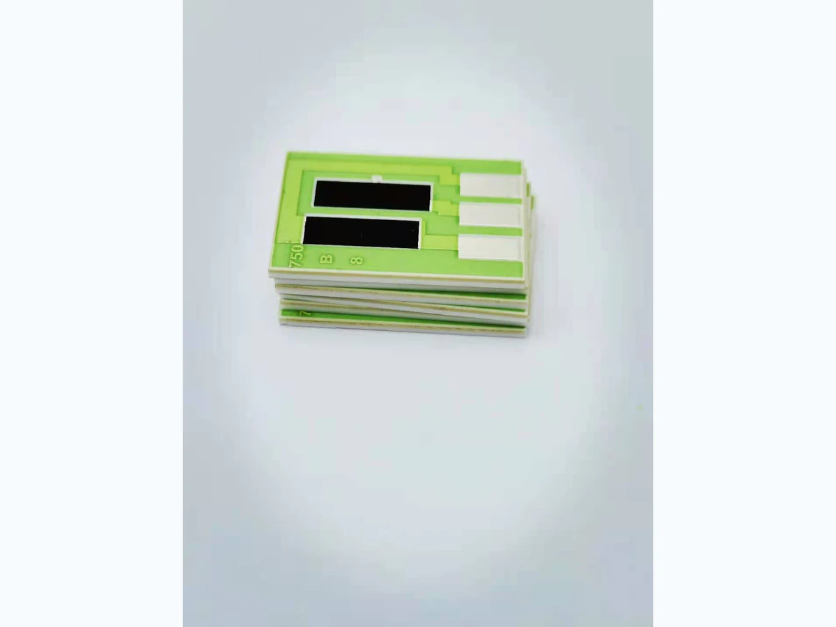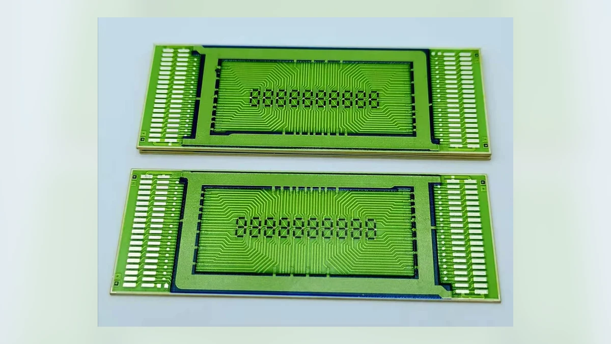
Thick-film and thin-film circuits can use the same ceramic outline yet behave very differently in cost, feature definition, resistor performance and production scale. The correct choice begins with the function and tolerance budget, not with the familiar name of a process.
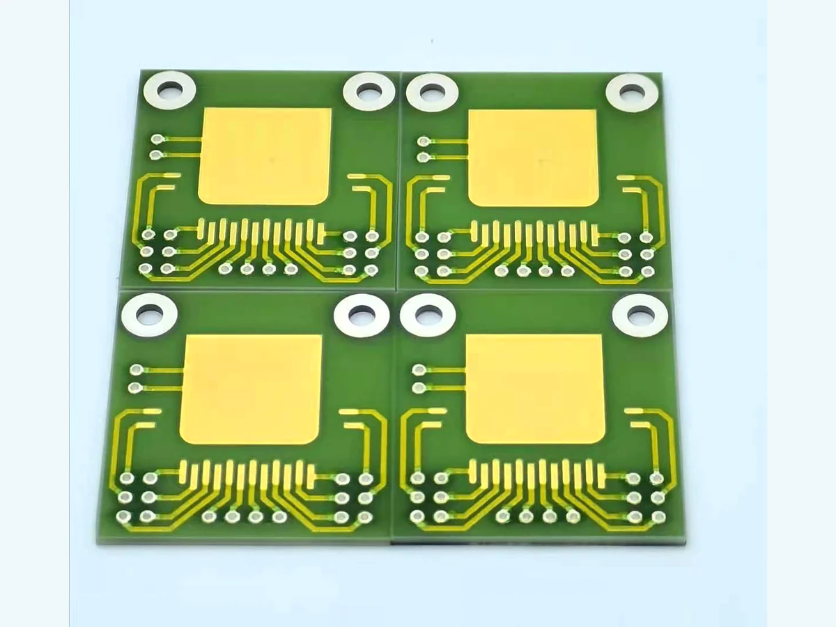
The substrate is the mechanical foundation, dielectric barrier and primary heat path of a ceramic circuit. Selecting it by material name alone misses the properties that actually control printing, firing, assembly and field reliability.
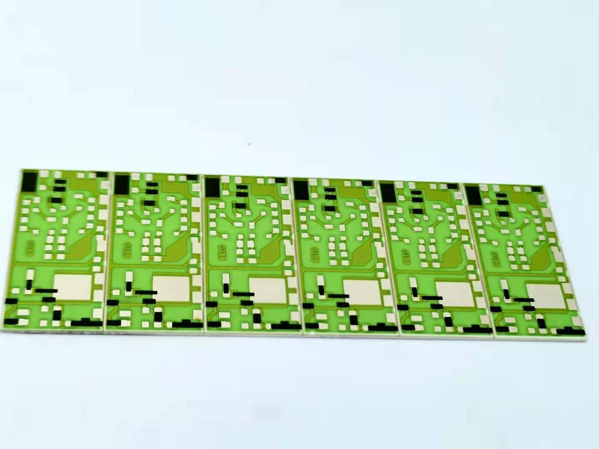
Printed resistor design starts with a simple relationship—resistance equals sheet resistance multiplied by the number of squares—but production accuracy depends on geometry, firing, contacts, temperature coefficient and trim access.
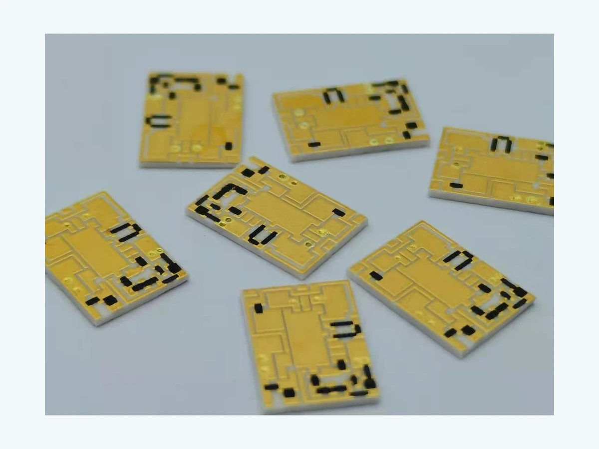
A schematic describes electrical intent; a manufacturable thick-film layout must also reserve space for printing, registration, firing, trimming, assembly, inspection and heat flow. The conversion is an engineering workflow, not a drawing exercise.
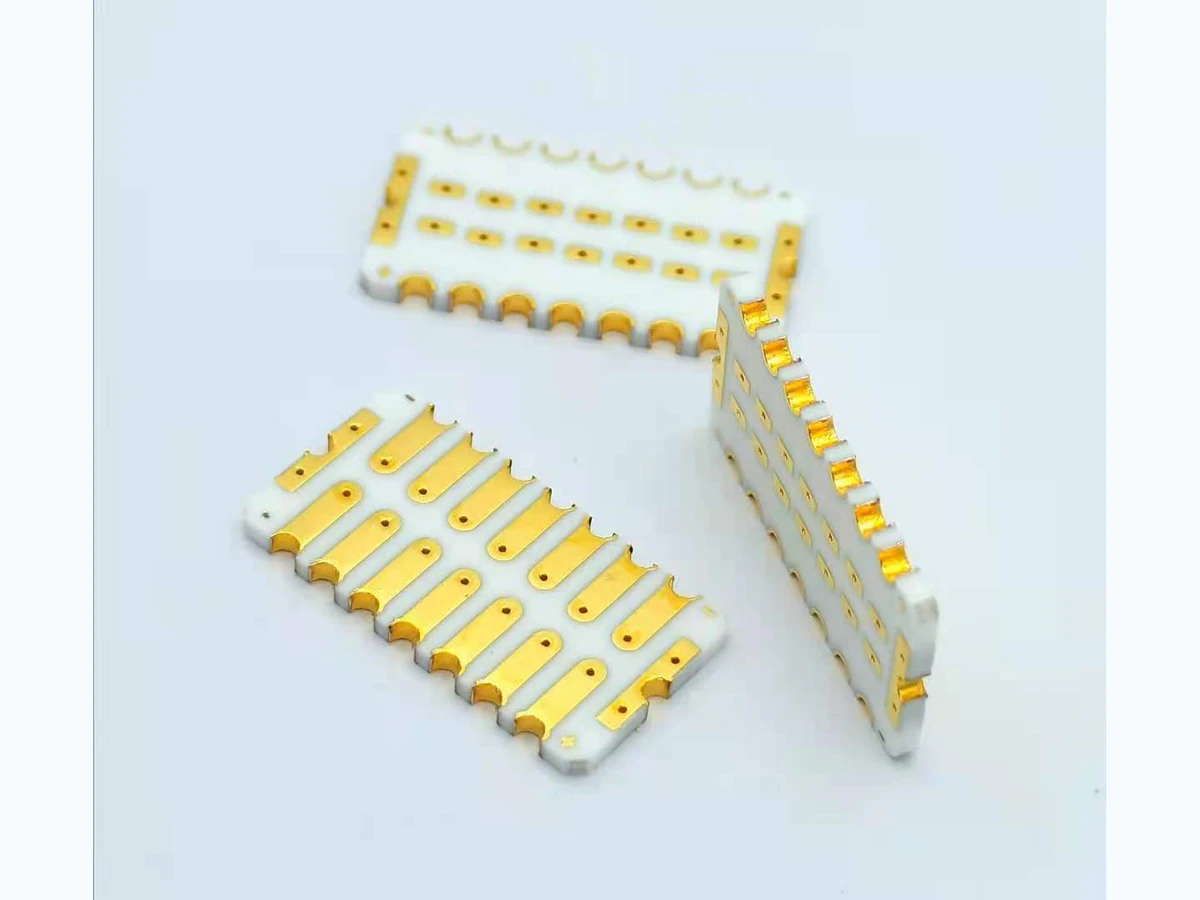
Conductor artwork on ceramic must carry current, survive firing and support the intended joining process. Line width is only one variable; material, fired thickness, transitions, pad geometry and interface testing complete the design.
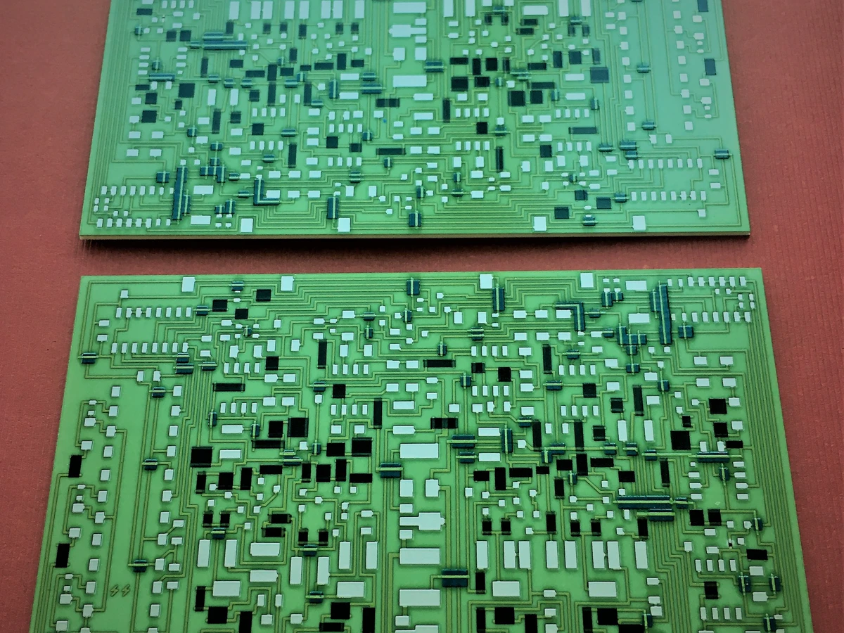
Printed dielectric makes it possible to cross conductors, isolate layers and build compact multilayer ceramic circuits. Reliability depends on coverage, registration, firing compatibility, via design and inspection of interfaces that later become hidden.
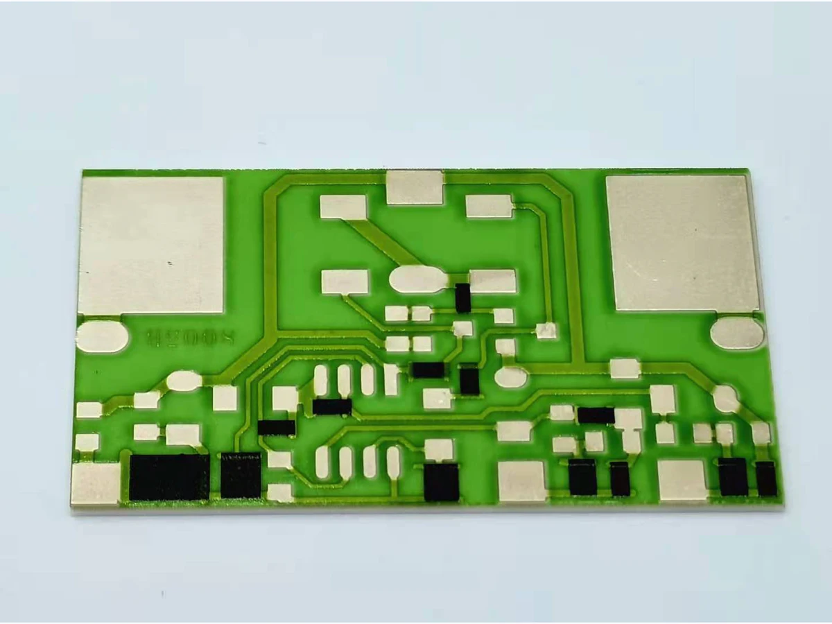
An engineer-written guide to sheet resistance, effective squares, initial resistor calculation, fired-process variables, measurement conditions, and laser-trim planning.