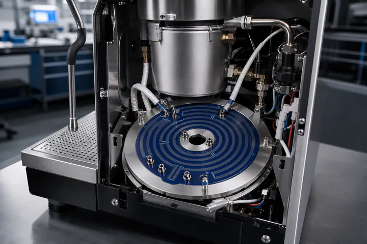
Drawing and design traceability
Heater geometry, voltage, power, resistance target, terminal layout, sensor interface, and drawing revision can be linked to the project record.

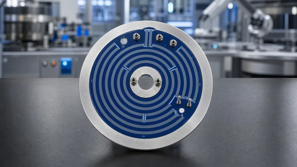
Coffee Machine Thick Film Heater
Chipsimple develops low-profile stainless steel heater plates with printed dielectric, resistive, conductor, and protective layers for coffee makers, espresso boiler assemblies, and compact hot-water modules.
*Illustrative RFQ starting ranges, not stocked ratings. Final voltage, power, resistance, surface loading, and safety limits depend on the approved drawing, heat path, water conditions, and test method.
Overview
A printed thick film heater places the electrical insulation and resistive circuit directly on a thin stainless steel heat-spreading surface. This creates a low-profile heating structure with short thermal distance, flexible watt distribution, and geometry that can follow a boiler, hot-water plate, or compact appliance module.
Coffee-machine projects must be reviewed as a complete thermal and safety system. The heater layout is linked to water volume or flow, heat-up time, clamping, scale, sensing, terminals, grounding, dry-run protection, and the appliance maker's qualification plan. A drawing and operating profile are therefore more useful than selecting a generic wattage alone.
Specifications
These are preliminary design routes rather than universal catalog limits. Final capability is confirmed from the heater outline, printed stack, terminals, heat transfer, water conditions, protection strategy, and appliance test plan.
| Substrate route | 430 stainless steel typical; 304 or 316L reviewed for the corrosion and assembly interface |
|---|---|
| Heater geometry | Round, annular, rectangular, or custom profile from 2D and 3D drawings |
| Substrate thickness | 0.5 mm to 1.5 mm typical starting range; final value depends on strength and heat path |
| Rated voltage | 100-240 VAC typical appliance route; low-voltage DC designs reviewed separately |
| Power target | 500-3,000 W typical discussion range; sized from water volume, flow, and heat-up target |
| Surface loading | Calculated from active area, thermal contact, water path, scale condition, and dry-run margin |
| Resistance tolerance | ±5% typical production target; tighter windows require process and measurement review |
| Printed layer stack | Insulating dielectric, resistive heater, conductor or bus layer, and protective overglaze |
| Termination options | Threaded studs, pins, welded or brazed leads, or project-specific bus connections |
|---|---|
| Temperature sensing | NTC, RTD, thermostat, thermal fuse, or external control interface by system design |
| Electrical safety | Withstand, insulation resistance, leakage, and grounding tests set by the appliance plan |
| Water-path interface | Printed circuit isolated from liquid; wetted materials validated at assembly level |
| Scale and cleaning | Water hardness, scale accumulation, descaling agent, and cleaning cycle included in review |
| System protection | No-flow, boil-dry, over-temperature, and thermal-cutoff logic defined with the appliance maker |
| Typical validation | Resistance, power, thermal map, leakage or hipot, thermal cycling, and scale-water testing |
| Prototype lead time | Confirmed after drawing, material route, tooling, quantity, and validation plan are released |
Manufacturing Capability
The printed stack and firing route must keep electrical insulation, heater resistance, conductor attachment, stainless steel behavior, terminal integration, and application testing aligned.
Voltage, power, water volume or flow, heat-up time, available area, mounting pressure, sensing, and safety targets are reviewed before layout.
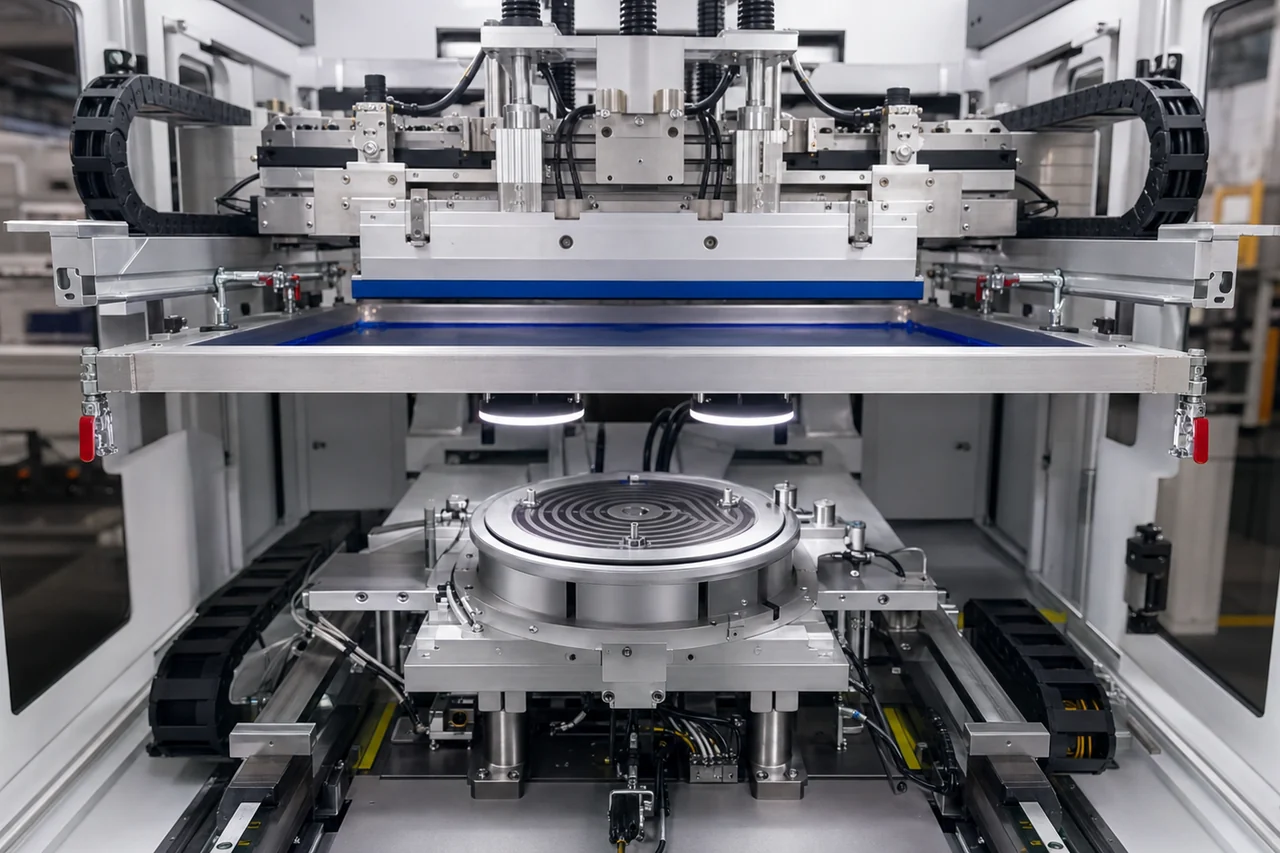
Insulating dielectric, resistive heater, conductor, and protective layers are printed with controlled screens, paste, fixtures, and registration.
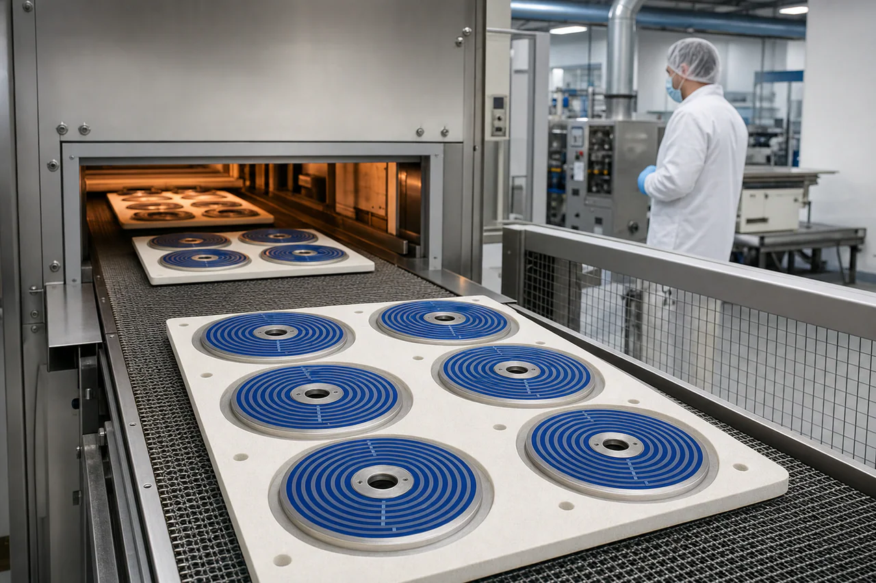
Each printed layer follows a defined drying and firing route so insulation, adhesion, resistance, and geometry remain compatible.
Terminals and sensor interfaces are assembled before resistance, power, insulation, leakage, thermal profile, and application tests.
Applications
Stainless steel thick film heater plates are selected when compact structure, fast response, custom watt distribution, and direct thermal contact are important to the appliance design.
Compact water-heating and keep-warm modules reviewed for voltage, water path, heat-up time, and dry-run protection.
Circular or custom heater plates designed around boiler contact, thermal sensors, mounting pressure, and recovery time.
Low-profile heating structures for compact appliance packaging and repeatable short brewing cycles.
Heater circuits matched to tank or flow-through assemblies, thermal cutoffs, and market-specific appliance testing.
Auxiliary heating zones reviewed for temperature control, cleaning chemistry, moisture, and electrical isolation.
Shared stainless heater architectures adapted by power, terminals, sensing, mechanical interface, and validation plan.
Trust Evidence
Evidence should match the approved heater drawing and the real appliance environment. Component checks support, but do not replace, final coffee-machine certification and functional validation.
Heater geometry, voltage, power, resistance target, terminal layout, sensor interface, and drawing revision can be linked to the project record.
Resistance, continuity, insulation resistance, dielectric withstand, leakage, and grounding checks are selected from the approved test plan.
Heat-up time, temperature distribution, steady-state behavior, recovery, and dry-run response can be documented during validation.
Water path, sealing, scale, corrosion, descaling chemistry, condensation, and cleaning exposure are reviewed with the complete assembly.
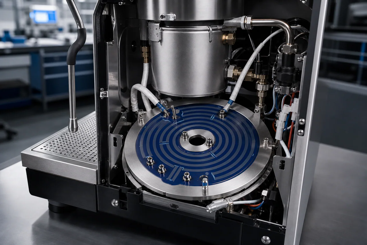
Representative layout for reviewing heater contact, mounting points, wiring clearance, sensor position, water tubing, and service access before tooling.
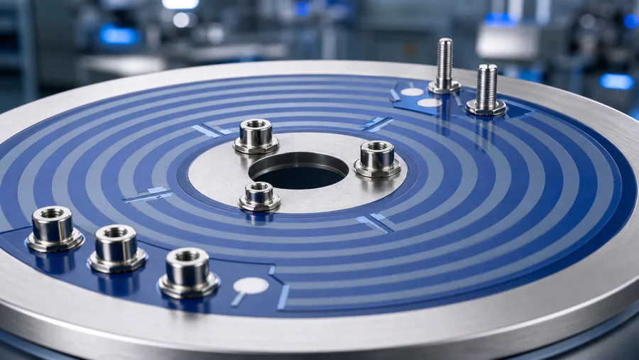
Terminal count, stud or lead construction, current path, clearances, protective glass, and connection direction are reviewed from the real drawing.
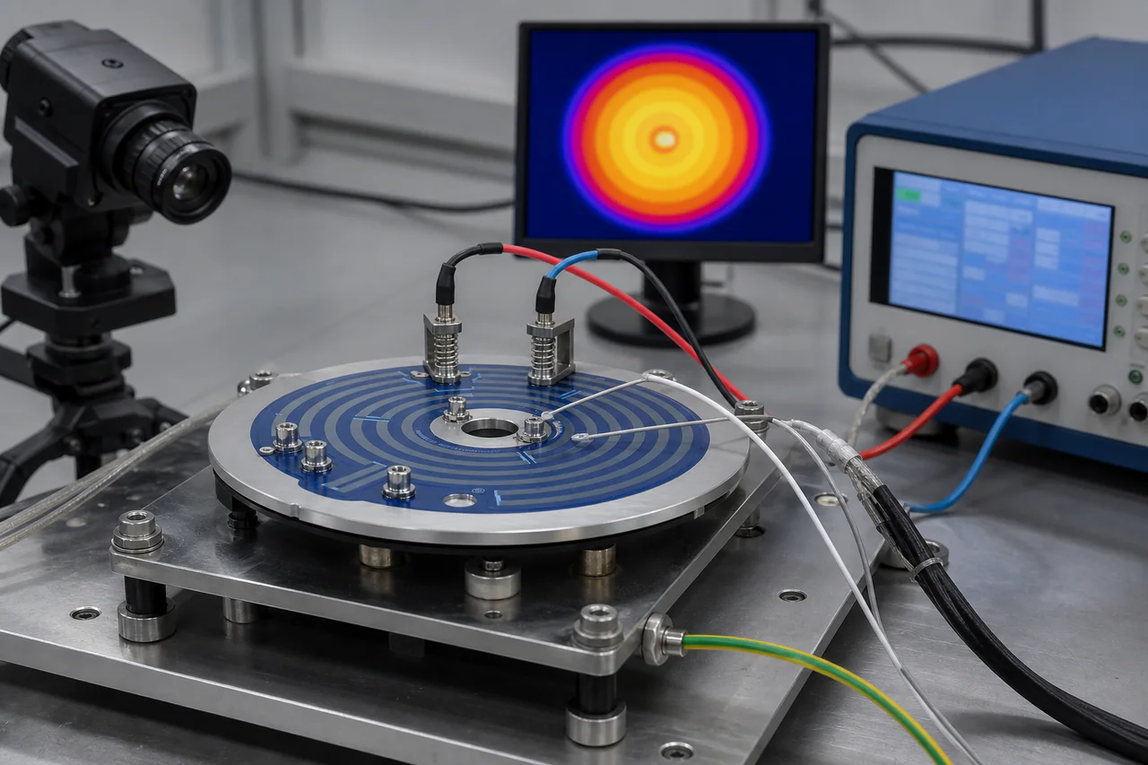
A project test plan can combine resistance and power data, thermal mapping, insulation, leakage, thermal cycling, and application-level functional checks.
Quality and Validation
Acceptance criteria can combine dimensions, print quality, resistance, power, insulation, dielectric withstand, leakage, grounding, temperature distribution, thermal cycling, scale-water exposure, and dry-run response. Limits are defined by the approved drawing and appliance test plan.
Request Quote
Use this form for a direct manufacturability and thermal review. Attach drawings or sample photos and include voltage, power, water conditions, heat-up target, mounting, sensing, protection, validation, quantity, and schedule.
RFQ Checklist
Share the complete appliance conditions when possible. If drawings are incomplete, measured sample photos, available installation space, voltage, target power, and water-heating requirements can start the review.
PDF, DWG, DXF, STEP, ZIP, Excel, Word, or measured sample photos are accepted.
Engineering Review
Send the assembly drawing, voltage, power, water or flow condition, sensing, safety targets, and quantity. Chipsimple will review the heater route before tooling or prototype planning.