Metal and dielectric stack
Confirm stainless alloy, plate thickness and flatness, surface preparation, dielectric material and coverage, print and thermal-process sequence, protection, and corrosion exposure.

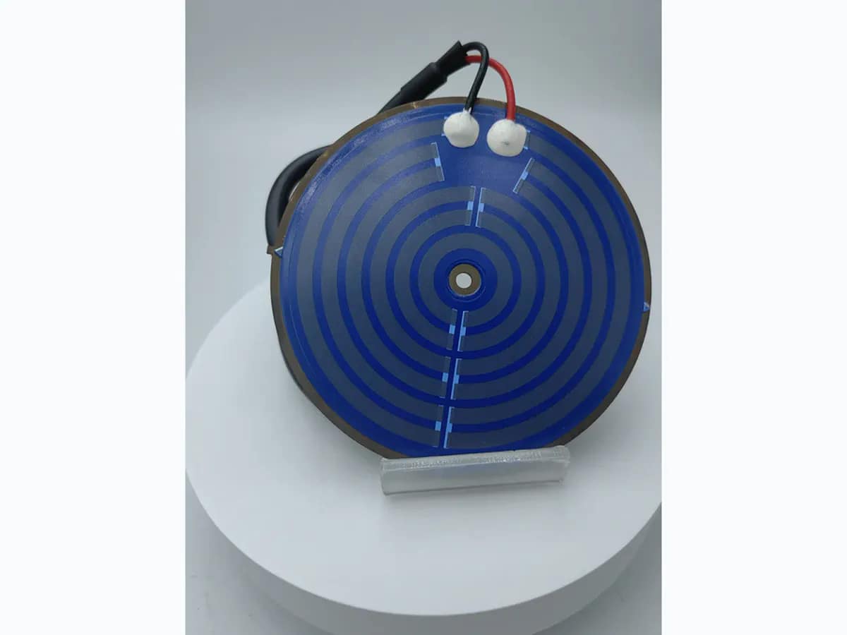
Metal-substrate printed heating plate
Stainless steel thick film heating plates combine a robust metal heat spreader with dielectric insulation and a printed heater pattern for compact thermal assemblies. Chipsimple reviews alloy and plate geometry, insulation stack, resistance, voltage, power zones, terminals, grounding, mounting, target temperature, heat-up time, fluid or air conditions, and safety tests together.
A custom steel heating plate with a compatible dielectric and printed heating circuit. Plate geometry, terminal arrangement and operating conditions are reviewed as one assembly.
Send plate drawing and steel grade, heating footprint, voltage and power, fluid or contact boundary, mounting, sensing and terminal layout, insulation criteria and quantities.
Send DrawingsA calculation-led engineering method for steel-heater layer calculation, from boundary definition and measurement through failure discrimination, validation, and RFQ inputs.
Compare bare and dielectric-coated steel through matched firing stages to locate residual shape change without treating curvature as measured film stress.
Evaluate post-assembly bending and indentation of stainless thick-film heaters through coating strain, electrical isolation retention and controlled mechanical comparisons.
Assign the pressure load path, seal movement, dry dielectric region and electrical protection interfaces of a steel heater fluid module.
Define ceramic support, compliant clamp reactions and thermal/electrical interfaces when a passive process block is removed from a fixed alumina heater.
A calculation-led engineering method for scale-maintenance trigger selection, from boundary definition and measurement through failure discrimination, validation, and RFQ inputs.
Verified capability review
Stainless Steel Thick Film Heating Plate is shown against approved company capability control sheets.
Capability source: approved company category control sheets. Final values remain drawing- and sample-controlled.
| Parameter | Standard capability | Engineering review range | Final release |
|---|---|---|---|
| Substrate Material | Stainless steel | Alternative approved route selected from heat path, insulation, corrosion, outline, mounting, and process compatibility | Approved material specification, drawing, and incoming criteria |
| Dielectric Layers | 3–4 printed dielectric layers typical | Layer count, fired thickness, edge margin, creepage, clearance, grounding, and interface by safety review | Released insulation stack and agreed IR/withstand test plan |
| Heater Resistor | RuO₂ / Metal-based / PTC | RuO₂, metal-based, or PTC route selected for resistance, temperature coefficient, firing/cure, and duty profile | Released drawing and approved sample |
| Conductor System | Ag / Ag-Pd / Metal terminal | Ag, Ag-Pd, or metal terminal route by current, connection, temperature, corrosion, and assembly | Approved material stack, assembly interface, and sample |
| Rated Voltage | Project-rated after electrical and thermal review | Approved category engineering envelope: 3–240 V AC/DC typical | Approved electrical-thermal design and instrumented prototype validation |
| Rated Power | Project-rated after electrical and thermal review | Approved category engineering envelope: 1–2,000 W typical; heat load and available area are checked | Approved electrical-thermal design and instrumented prototype validation |
| Parameter | Standard capability | Engineering review range | Final release |
|---|---|---|---|
| Target Resistance | Project-rated after electrical and thermal review | Approved category engineering envelope: 0.1 Ω–10 kΩ typical; calculated from released voltage and power | Released electrical limits, measurement method, and approved sample |
| Resistance Tolerance | ±5% typical | ±5% typical; reference temperature, lead compensation, and measurement timing are defined | Released electrical limits, measurement method, and approved sample |
| Power Density | Project-rated after electrical and thermal review | Approved category engineering envelope: 1–60 W/cm² typical; local cooling, duty, contact, and hot spots are reviewed | Approved electrical-thermal design and instrumented prototype validation |
| Operating Temperature | Ceramic/metal route ≤600°C typical | Continuous, peak, ambient, fluid, interface, and no-flow/no-load conditions are separated for validation | Approved electrical-thermal design and instrumented prototype validation |
| Process Temperature | ≈590°C metal-substrate process route | Actual peak, dwell, atmosphere, and refire/cure exposure follow the selected material stack | Approved material-process route and production traveler |
| Electrical Test | IR ≥100 MΩ / Hi-pot ≥1.5 kVAC typical | IR, hi-pot voltage, ramp, dwell, leakage, humidity state, and pre/post conditioning by product safety plan | Released insulation stack and agreed IR/withstand test plan |
| Life-test conditions | On/off cycling is defined with powered dwell, cooling dwell, mounting, cooling medium, and starting temperature | Cycle count, voltage, load, fault conditions, resistance drift, insulation, leakage, and appearance limits by application risk | Agreed endurance profile and pre/post-test acceptance report |
A stainless heating plate is an electrothermal system with coupled insulation and heat-transfer requirements. Engineering review connects plate geometry, dielectric coverage, heater artwork, current density, edge and hole clearances, terminals, grounding, mounting pressure, heated body, fluid or airflow, sensor and controls, dry-run risk, thermal cycling, and safety limits.
Confirm stainless alloy, plate thickness and flatness, surface preparation, dielectric material and coverage, print and thermal-process sequence, protection, and corrosion exposure.
Release resistance paths, power zones, no-heat areas, holes, edges, terminal pads, sensor location, grounding features, and alignment datums with electrical clearances.
Define lead or terminal attachment, strain relief, connector, grounding, clamp or bond method, pressure, interface material, heated body, sealing, and assembly sequence.
Specify resistance, insulation, hi-pot, leakage, grounding, power, heat-up, temperature map, dry-run or fluid tests, cycling, fixture, sampling, and failure limits.
Metal heating plates suit fast-response appliance and industrial assemblies when heat transfer, fluid or air conditions, mounting, controls, and electrical safety are validated together.
Application images are engineering illustrations, not customer projects, production records, or evidence of a released design. Suitability is confirmed only after the drawing, interfaces, operating conditions, risks, and validation plan are reviewed.
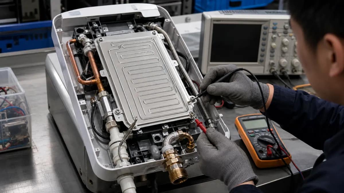 Application illustration
Water-heating modules require controlled flow, pressure, scale exposure, dry-run protection, grounding, leakage, temperature control, sealing, and lifecycle validation.
Review application inputs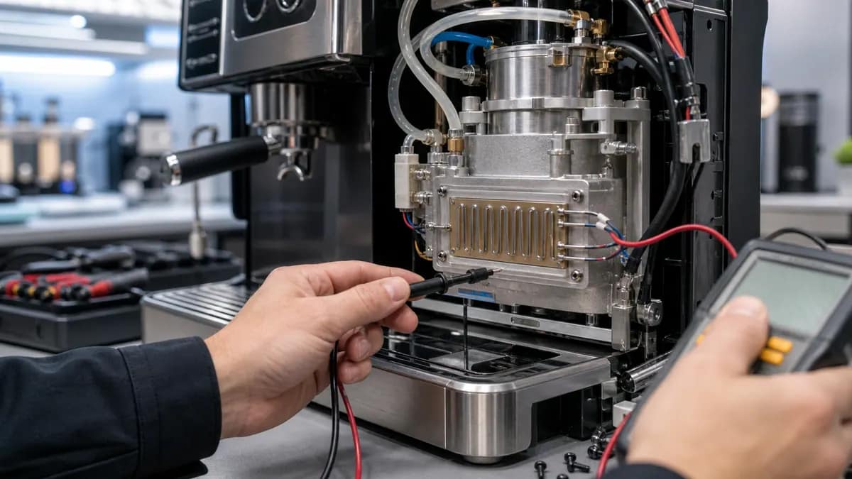 Application illustration
Coffee systems need application-specific fluid path, temperature profile, scale and cleaning exposure, mounting, controls, terminal protection, and safety testing.
Review application inputs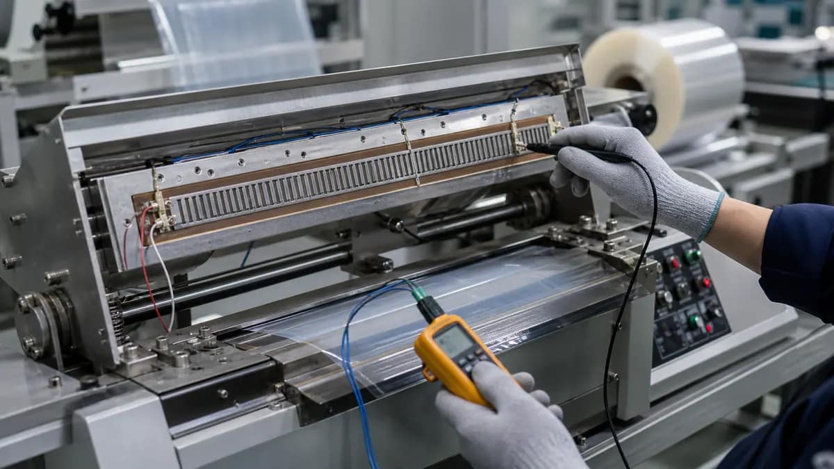 Application illustration
Sealing plates require defined contact pressure, temperature uniformity, cycle time, surface interface, contamination, controls, and production-duty validation.
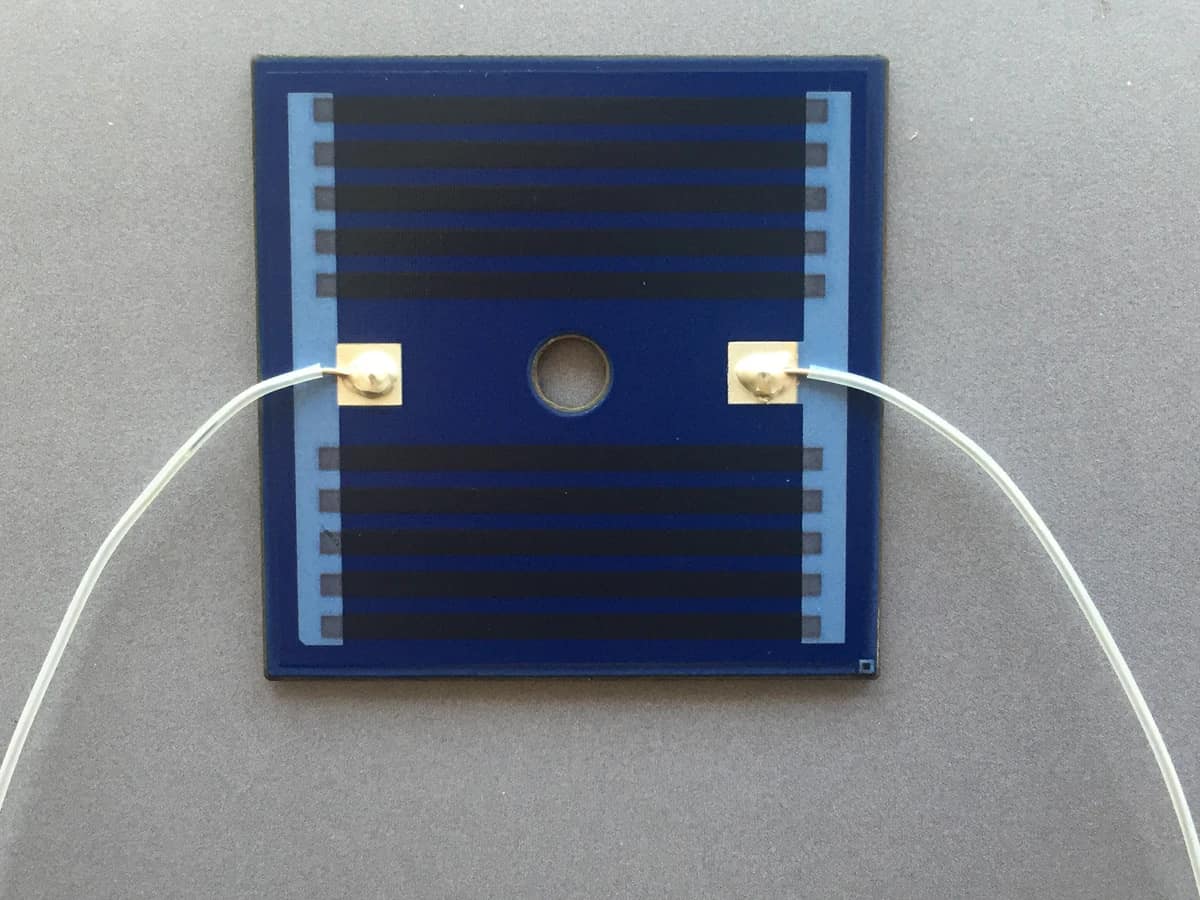
Review application inputsThe verified photographs show square blue printed heater areas, parallel dark resistance paths, conductor terminations, white leads, center holes, and one plate attached to a larger metal body. These visible features do not prove stainless grade, dielectric construction, resistance, voltage, power, temperature, insulation, grounding, or lifecycle.
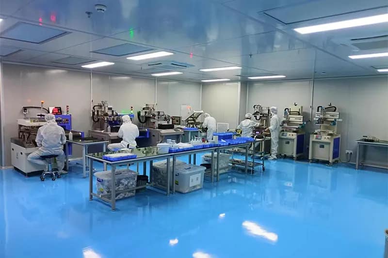
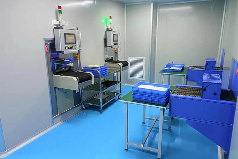
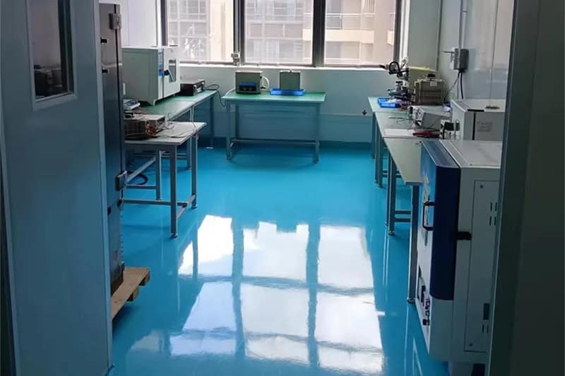
Chipsimple supports controlled heater printing, thermal processing, laboratory inspection, and protected packing in Dongguan.
Stainless heating-plate projects release the metal and dielectric stack, artwork, terminals, grounding, mounting, electrical tests, thermal fixture, sampling, traceability, and acceptance records together; final ratings depend on validated assembly conditions.
Short answers for quotation planning; released drawings and validation requirements remain controlling.
Define stainless alloy, plate size and thickness, heater zones, resistance, voltage, power, target temperature, heat-up time, duty, holes and no-heat areas, terminals, grounding, sensor and controls, mounting, heated body, fluid or airflow, sealing, corrosion, insulation, leakage, and safety requirements.
No. They are practical category-level selection values, not a released product specification. Material compatibility, geometry, print build, electrical loading, assembly, environment, inspection method, and expected volume can narrow the usable window. Final values are confirmed against the controlled drawing and approved project conditions.
Test resistance, insulation, hi-pot, leakage and grounding as applicable, actual power, terminal temperature, heat-up and cool-down, temperature map, mounting effects, fluid-flow or dry-run behavior, control response, corrosion or scale exposure, and thermal cycling in the production-intent assembly.
Send the controlled drawing or artwork, dimensions and tolerances, material preference, electrical targets, assembly interface, operating environment, validation requirements, prototype quantity, annual volume, and schedule. Include the metal alloy, dielectric and grounding requirements, fluid or air condition, mounting, power map, controls, and safety-test plan.
Send the heater and assembly drawings with fluid or air conditions, mounting, controls, grounding, safety limits, and validation targets. Resistance and power can be reviewed only when the dielectric stack and real heat path are defined; free-air values do not release the finished heating module.
PDF, DWG, DXF, STEP, Gerber, ZIP, Excel, Word, or sample photos are accepted.
The drawing-upload form loads as you reach this section.