
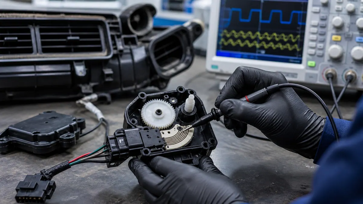
A thick film ceramic PCB combines a ceramic substrate with fired conductive, resistive, dielectric, or protective layers. It is usually considered when ordinary FR4 PCB technology cannot meet the required thermal stability, high-temperature operation, integrated resistor function, or harsh-environment reliability.
Basic composition
- Substrate: alumina is widely used for cost-effective ceramic circuits; aluminum nitride is selected when heat spreading is a major requirement.
- Conductive layers: silver, silver-palladium, gold, or other paste systems are selected according to soldering, bonding, migration risk, and cost.
- Resistive layers: printed resistor paste can form fixed resistors, resistor networks, sensor tracks, and heater patterns.
- Dielectric and protection layers: insulation, crossover, overglaze, and protective coatings can be printed where the application requires them.
Manufacturing process overview
The typical route includes substrate preparation, screen printing, drying, firing or sintering, optional multilayer printing, optional laser trimming, singulation, inspection, and electrical testing. Some products are designed as non-trimmed fired resistor patterns, while precision circuits may require passive or functional trimming.
Why buyers choose thick film ceramic PCB
- Better heat resistance and dimensional stability than organic PCB materials.
- Integrated printed resistors, heaters, or sensor tracks on the substrate.
- Compact circuit geometry for automotive, industrial, medical, and power modules.
- Good insulation and stable substrate behavior under thermal cycling.
- Potential for custom shapes such as arc, strip, round, slotted, or compact hybrid substrates.
Limitations to review
Thick film ceramic PCB is not automatically the best choice for every circuit. It may cost more than FR4, require custom screens and fixtures, have different line/space rules, and need careful material-stack review. Ceramic is also brittle, so outline, holes, slots, and assembly handling must be designed carefully.
Typical applications
- Fuel level sensor ceramic circuits and rotary position sensor resistive elements.
- Throttle position sensor resistor tracks and custom output-curve circuits.
- Stainless steel, ceramic, aluminum, and PI thick film heating modules.
- LED thermal substrates, power electronics, and compact high-temperature modules.
- RF, microwave, industrial, and medical hybrid ceramic circuits.
RFQ checklist
- Substrate material, thickness, size, holes, slots, and outline tolerance.
- Printed conductor, resistor, dielectric, and protective layer requirements.
- Resistance value, output curve, tolerance, TCR, power, and trim or non-trim route.
- Operating voltage, current, temperature, humidity, vibration, fuel/oil exposure, and cleaning environment.
- Assembly method: soldering, bonding, spring contact, connector, die attach, or housing integration.
- Prototype quantity, annual volume, target lead time, and inspection or reliability standard.