Thick film circuit manufacturing is a controlled sequence of material preparation, printing, thermal processing, trimming, assembly, and testing. The same schematic can perform very differently if the paste system, substrate, screen, firing profile, or trimming path is changed.
1. Substrate preparation
The process starts with a substrate such as alumina, aluminum nitride, stainless steel, aluminum, or flexible PI depending on the product. Cleaning and surface condition are important because they affect paste wetting, film adhesion, conductor continuity, and dielectric integrity.
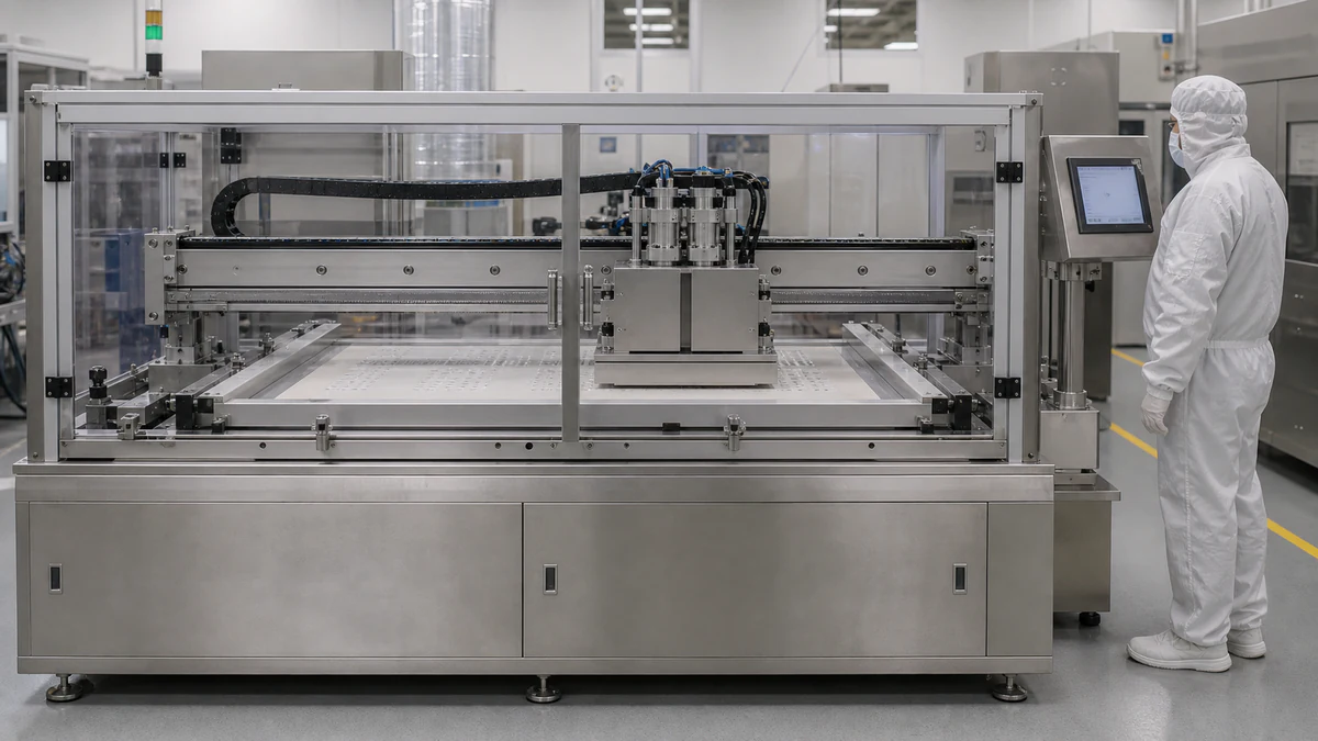
2. Screen printing
Conductive, resistive, or dielectric paste is transferred through a patterned screen or stencil. Mesh, emulsion thickness, squeegee pressure, snap-off distance, paste viscosity, and print speed affect line edge definition and fired film thickness.
3. Drying
Drying removes volatile organic carriers before firing. Poor drying can cause blistering, pinholes, cracks, or film distortion during firing.
4. Firing or sintering
Firing burns out organics and develops the final film structure. Temperature profile, peak temperature, belt speed, atmosphere, and cooling rate influence adhesion, sheet resistance, TCR, dielectric strength, and long-term stability.
5. Multilayer printing
Multilayer thick film circuits may repeat conductor and dielectric printing to create crossovers, insulation, or compact interconnects. Registration and dielectric reliability become critical.
6. Laser trimming
Printed thick film resistors are commonly trimmed after firing. Passive trimming adjusts resistance value; active trimming adjusts a powered circuit output. Trim path, laser power, pulse rate, and heat affected zone influence drift and stability.
7. Assembly and test
Depending on the product, components may be soldered, bonded, attached, or encapsulated. Inspection includes visual checks, resistance measurement, insulation testing, adhesion checks, thermal tests, and application-specific reliability screening.