Thick film PCB, ceramic PCB, and thin film circuit are related terms, but they are not identical. Selecting the right technology depends on electrical precision, thermal path, conductor geometry, resistor stability, volume, cost, and qualification requirements.
| Technology | Best meaning | Typical use |
|---|---|---|
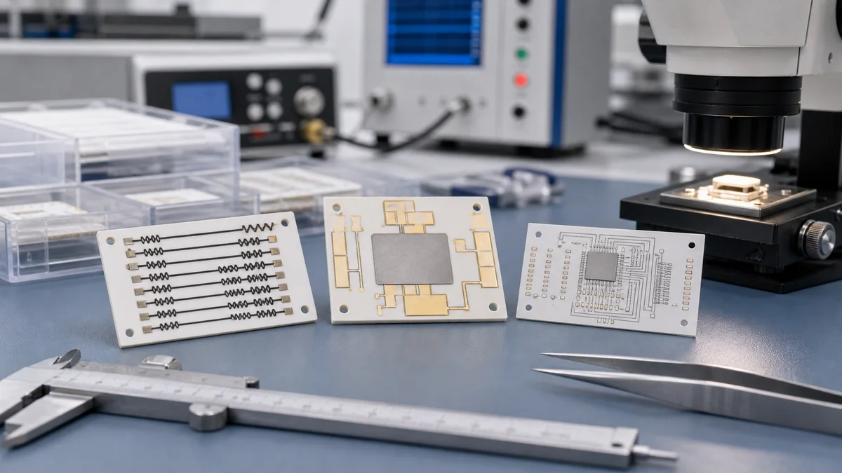
| Thick film PCB | Printed and fired conductor, resistor, and dielectric paste patterns on a substrate. | Sensor resistors, heaters, ceramic circuits, hybrid modules. |
| Ceramic PCB | A circuit substrate using ceramic such as alumina or AlN. It may use thick film, DPC, DBC, AMB, or other metallization. | Power modules, LED thermal boards, high-temperature circuits. |
| Thin film circuit | Vacuum deposited metal and resistor films patterned by photolithography and etching. | High precision, high frequency, fine-line networks. |
Precision and geometry
Thin film generally supports finer geometry and higher resistor precision. Thick film is more economical and robust for printed resistor networks, heater patterns, and medium-to-high volume ceramic circuits where screen printing and firing are appropriate.
Thermal behavior
Ceramic substrates such as alumina and aluminum nitride offer better high-temperature and thermal cycling behavior than FR4. AlN is selected when thermal conductivity is the dominant requirement. Alumina is often chosen for cost-effective thick film sensor and resistor circuits.
Cost and production fit
Thick film is attractive for custom OEM products that need printed functional elements and repeatable batch production. Thin film is used when the project demands very tight tolerances, fine line patterns, or high-frequency precision that justifies the process cost.
Selection summary
- Choose thick film for printed resistors, heaters, robust ceramic hybrids, and application-specific circuits.
- Choose ceramic PCB when the substrate thermal path is the primary requirement and metallization can vary.
- Choose thin film when precision, fine features, or RF performance dominate the design.