
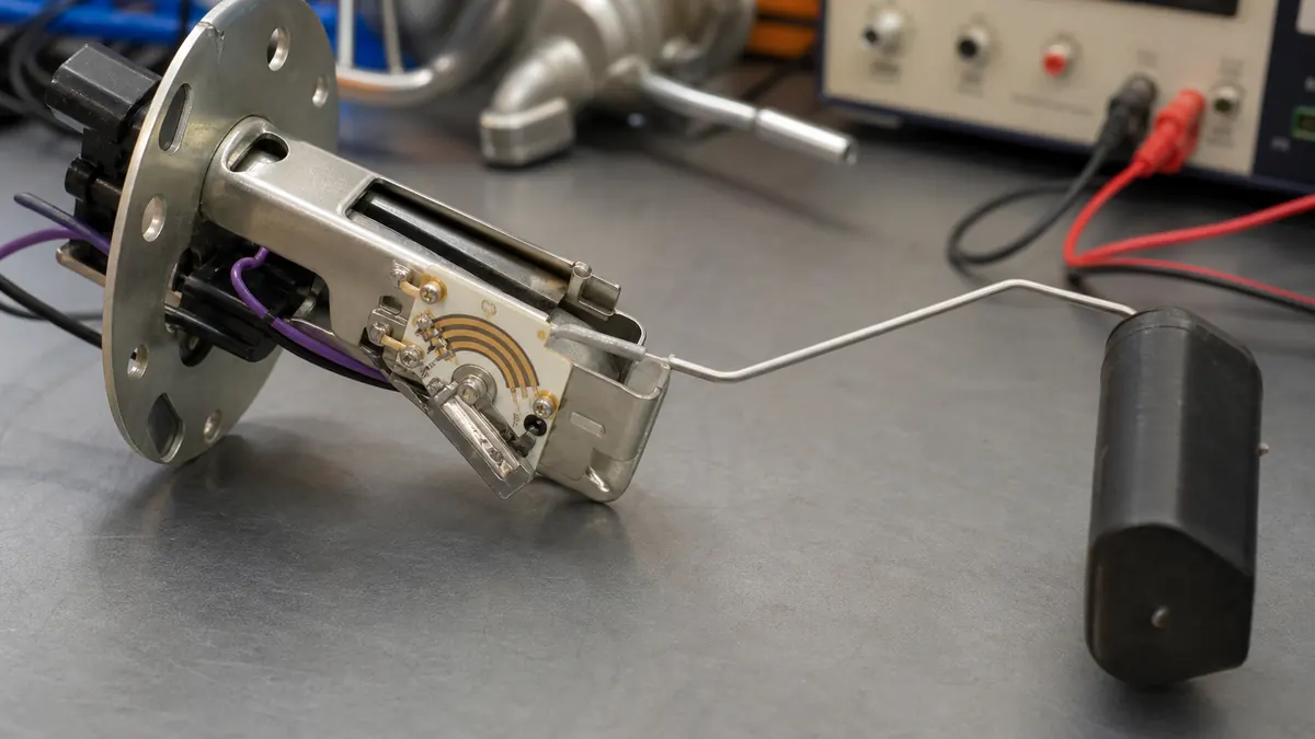
Position sensors often depend on a stable resistive element and a reliable contact or collector structure. For thick film manufacturing, the resistive pattern is a controlled electrical path with silver terminations, overlap zones, collector tracks, contact areas, protective glass, and application-specific geometry.
Common resistive element shapes
- Arc track: rotary angle sensing, throttle position feedback, fuel level sensing, and lever mechanisms.
- Linear track: straight displacement sensing with a defined output relationship.
- Multi-track element: redundant outputs, switch zones, warning ranges, or independent signal curves.
- Segmented resistor network: stepped, compensated, or application-specific resistance behavior.
Silver termination overlap matters
In a real thick film resistive element, resistor paste normally overlaps the silver termination area by a controlled amount. This overlap helps create a stable electrical transition between the resistor body and the terminal pad. A drawing should define the silver electrode, resistor body, overlap area, and usable contact zone clearly enough for production review.
Collector and wiper paths
Contact-type sensor circuits may use a separate silver collector track or contact pad area. The collector must be isolated from the resistive track except through the intended moving contact or wiper. Good designs keep visible ceramic clearance between nets and avoid ambiguous bridges that could be misread as short circuits.
Design data needed for RFQ
- Mechanical stroke or rotation angle.
- Resistance value, output curve, tolerance, and linearity requirement.
- Wiper/contact type, contact force, expected cycle life, and operating environment.
- Substrate material, outline, holes, mounting, terminal style, and connector requirement.
- Temperature, humidity, vibration, fuel/oil exposure, and target validation plan.