
On this page
Prepared by Chipsimple Engineering Team, Engineering and technical content review
Published online August 8, 2026 · Reviewed August 8, 2026
Safety boundary: A heater substrate cannot be declared safe from resistance and wattage alone. The equipment manufacturer is responsible for the final protection concept, insulation coordination, controls, abnormal-operation analysis, certification, and applicable product standard.
A thick film heater converts electrical power into heat in a printed resistive pattern on a ceramic or insulated metal substrate. The basic equations are familiar, but a reliable design depends on where heat goes. At a specified voltage, resistance sets nominal power through P = V²/R. That calculation does not predict surface temperature. Temperature results from power distribution, substrate and film properties, mounting, interface resistance, heated medium, airflow or liquid flow, control logic, ambient conditions, and heat loss.
Translate the application into boundary conditions
A useful specification begins with the job: heat a mass, maintain a surface, warm flowing fluid, prevent condensation, or control a thermal zone. Define starting and target temperatures, allowable warm-up time, steady and transient duty, heated mass or flow rate, ambient range, permitted non-uniformity, and sensor location. Include the mechanical stack and thermal interface.
Rated voltage is not enough. Provide the actual voltage range, waveform or drive method, switching strategy, tolerance, and relevant abnormal supply conditions. If control uses pulse-width modulation, phase control, or cycling, local thermal response and electrical stress still need assessment. Leads, terminals, connectors, and current paths must support the same duty.
Power density is local
Dividing total power by total substrate area can hide hot regions. Track width, spacing, turns, terminal transitions, neck-downs, cut-outs, mounting points, and local cooling determine current density and heat flux. Corners and conductor-resistor interfaces deserve attention. A design can have acceptable average power density while a small section runs much hotter.
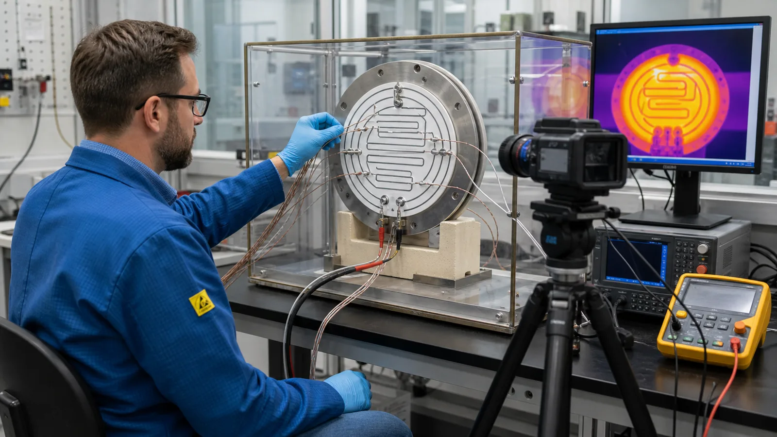
Thermal simulation can guide layout, but it needs realistic properties and interface assumptions. Prototype thermal mapping then checks the model in the intended assembly. Record sensor type, emissivity treatment for infrared measurements, sampling rate, warm-up state, input power, ambient condition, mounting pressure, and actual medium or load. A thermal image without those conditions is incomplete evidence.
Insulation is a stack, not a coating label
For metal-substrate heaters, dielectric layers separate the live printed system from base metal. Pinholes, edge coverage, overlap, fired thickness, surface condition, damage, humidity, and repeated thermal expansion can affect performance. Multiple printed layers may be used, but layer count is not a substitute for a released dielectric specification and validated process.
Clearance and creepage requirements depend on working voltage, overvoltage category, pollution degree, material group, altitude, waveform, and equipment standard. IEC 60664-1 provides principles, requirements, and tests for insulation coordination within its scope. It should be applied by the relevant designer; a component supplier should not invent a universal distance without system inputs.
Safety standards are selected by the end product
IEC 60335-1 addresses general safety for household and similar appliances and is used with the appropriate Part 2 for the appliance type. Industrial, medical, automotive, aerospace, and other equipment can fall under different standards. Review records the end product, market, standard and edition, insulation class, accessible parts, protective-earth strategy, temperature limits, and abnormal tests.
A heater may require independent protection such as a temperature sensor, thermostat, thermal fuse, current limit, flow or liquid-level interlock, software monitor, or redundant shutdown. Which measures apply is a system decision. The printed heater should be evaluated under foreseeable faults such as loss of cooling, dry operation, blocked airflow, detached sensor, stalled flow, or relay failure when relevant.
Build a staged validation plan
- Incoming and visual: dimensions, flatness, surface, dielectric coverage, print registration, terminals, and edge clearance.
- Electrical: resistance at a reference temperature, controlled-voltage power, insulation resistance, dielectric withstand, leakage, and earth continuity where applicable.
- Thermal: warm-up curve, steady-state map, zone uniformity, sensor correlation, control stability, and cool-down in the assembly.
- Environmental: temperature change, damp heat, fluid or cleaning exposure, mechanical load, and cycling selected for actual use.
- Abnormal operation: relevant loss-of-load or loss-of-cooling conditions with final protection devices and enclosure.
- Post-test: visual condition, resistance shift, insulation, terminal integrity, and function against agreed limits.
IEC 60068-2-14 provides a method for testing effects of specified temperature changes. It does not select temperatures, dwell, cycles, or pass criteria for a heater. Those severities belong in the customer qualification plan.
RFQ inputs that prevent false assumptions
Send the assembly drawing, substrate and envelope, voltage, target power or resistance, heated medium, flow or load, temperature targets, warm-up time, duty cycle, mounting, sensor, control method, protection devices, environment, applicable standard, required tests, and quantities. Mark which limits are mandatory and which remain engineering targets.
A heater project is released when electrical design, thermal path, insulation, controls, and test plan agree. Quoting wattage without those boundaries is not an engineering review.
Primary references
- IEC 60335-1:2020, Household and similar electrical appliances — Safety — Part 1 — general framework used with the appropriate Part 2.
- IEC 60664-1:2020, Insulation coordination — Part 1 — principles and tests for clearance, creepage, and solid insulation within its scope.
- IEC 60068-2-14:2023, Test N: Change of temperature — standardized temperature-change test method.
Review the complete heater assembly
Provide voltage, power, thermal target, load, mounting, sensing, protection, environment, applicable standard, and validation requirements.