
Chipsimple
Thick Film PCB for Fuel Level Sensor
Custom thick film PCB and ceramic resistor tracks for automotive and motorcycle fuel level sensors, fuel gauge circuits, and sender assemblies.
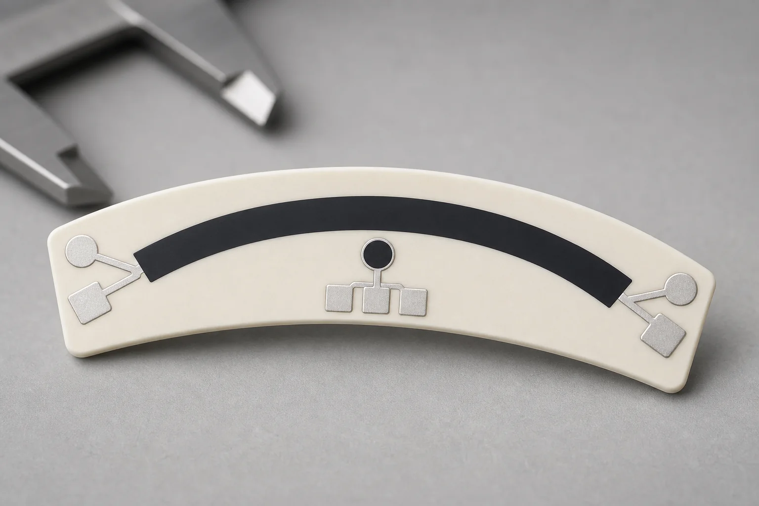
Chipsimple manufactures custom thick film PCB products for fuel level sensors, fuel gauge modules, and sender assemblies. These circuits usually use a ceramic substrate with a printed thick film resistor track that converts float movement or wiper position into a resistance signal for the instrument cluster or control system.
Fuel level sensor circuits need more than a simple board layout. The resistance curve, contact path, substrate size, terminal area, wiper pressure, fuel environment, operating temperature, and lifecycle target all affect final output stability.
Typical fuel level sensor thick film PCB parameters
The following values are normal RFQ review items for ceramic fuel sender circuits. Exact resistance curve and durability targets should come from the customer drawing, sample, or sensor assembly requirement.
| Parameter | Typical engineering range |
|---|---|
| Product type | Fuel gauge ceramic circuit, fuel sender resistor board, fuel level sensor thick film PCB |
| Substrate | Alumina ceramic, custom outline with holes, slots, or arc profile by drawing |
| Track geometry | Linear, arc-shaped, stepped, or non-linear resistance track matched to float travel |
| Output behavior | Customer-defined resistance range or table across travel angle or float position |
| Contact area | Designed for wiper contact path, terminal area, and mechanical sender structure |
| Environment | Fuel exposure, temperature cycling, vibration, humidity, and mechanical wear reviewed together |
| Inspection | Resistance value, curve check, continuity, contact surface, dimensions, and appearance |
Application scenarios
- Motorcycle fuel gauge ceramic thick film circuit boards.
- Automotive fuel level sensor resistor boards.
- Small engine, equipment, and industrial fuel sender modules.
- OEM replacement programs requiring matched resistance output.
- Custom level sensing assemblies where a ceramic resistor track is required.
Design review points
- Resistance range and curve table at defined float positions or travel angles.
- Contact path width, wiper material, pressure, and expected movement cycle.
- Substrate size, thickness, hole location, edge profile, and mounting structure.
- Fuel exposure, temperature range, vibration, humidity, and cleaning process.
- Terminal method, welding or soldering requirement, connector area, and final assembly constraints.
RFQ checklist
- Existing sample photo or 2D drawing of the ceramic resistor board.
- Resistance table, empty/full resistance target, movement angle, or float travel data.
- Substrate dimensions, hole position, contact path, terminal style, and assembly method.
- Fuel type, operating temperature, vibration condition, wear cycle, and validation requirement.
- Prototype quantity, expected annual volume, and target lead time.