
Chipsimple
Thick Film PCB for Throttle Position Sensor
Custom thick film PCB and printed resistor tracks for throttle position sensors, automotive position sensing modules, and stable signal output applications.
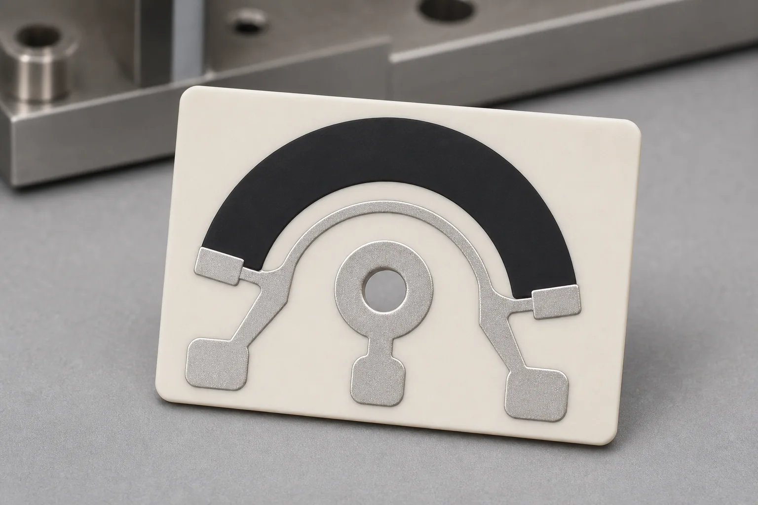
Chipsimple manufactures custom thick film PCB and printed resistor track products for throttle position sensors and related automotive position sensing modules. These circuits are designed to provide stable signal output as the sensor mechanism moves across the resistor pattern.
Throttle position sensor projects require coordinated review of resistance curve, contact track geometry, substrate material, conductor layout, mechanical travel, wiper behavior, operating temperature, and lifecycle target.
Typical throttle position sensor thick film PCB parameters
These are practical engineering discussion items for throttle sensor resistor boards. Final values should be confirmed with the customer's sensor structure, electrical output requirement, and validation standard.
| Parameter | Typical engineering range |
|---|---|
| Product type | Throttle position sensor resistor, position sensor thick film PCB, custom sensor track |
| Substrate | Ceramic substrate with custom shape, mounting holes, and contact geometry |
| Track geometry | Arc, crescent, linear, or application-specific resistor/contact path |
| Output behavior | Customer-defined resistance range, linearity, angle response, or signal curve |
| Contact design | Wiper path, terminal pads, conductor area, surface finish, and wear review |
| Environment | Engine compartment temperature, vibration, humidity, contamination, and lifecycle target by project |
| Inspection | Resistance value, curve behavior, continuity, dimensions, surface quality, and consistency |
Application scenarios
- Automotive throttle position sensor resistor circuits.
- Engine control position sensing modules.
- Industrial position sensors using printed resistor tracks.
- Custom control assemblies requiring compact resistance output.
- Replacement or OEM programs where a specific signal curve must be matched.
Design review points
- Target resistance range, linearity or curve table, and tolerance requirement.
- Mechanical travel angle, contact area, wiper pressure, and expected movement cycle.
- Substrate size, mounting holes, edge profile, terminal layout, and assembly constraints.
- Operating temperature, vibration, humidity, contamination risk, and lifecycle target.
- Testing method for resistance output, curve behavior, surface condition, and batch consistency.
RFQ checklist
- Sensor resistor drawing, original sample photos, or measured reference part.
- Resistance curve, travel angle, linearity expectation, tolerance, and signal output target.
- Substrate outline, thickness, holes, contact path, terminal pads, and assembly method.
- Working temperature, vibration, humidity, contamination, wear cycle, and validation standard.
- Prototype quantity, annual demand, and target lead time.