Fast local heat transfer
A thin printed stack on a metal or ceramic structure may reduce thermal distance, provided fluid contact, pressure, corrosion, insulation, and mounting are engineered together.

Application engineering guide
Design the heater around the fluid path, heat transfer, scale, pressure, sensing, grounding, dry-run protection, cleaning, and appliance safety plan.
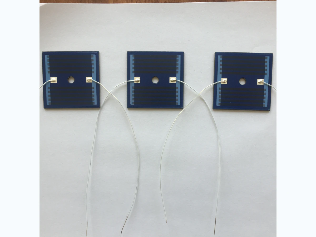
For water, beverage, steam, or surface-heating equipment, voltage and wattage do not define the design on their own. The fluid path, thermal contact, scale, pressure, housing, sensor position, flow detection, electrical protection, terminals, and cleaning cycle determine whether the heater can operate safely and repeatably.
Metal-base and ceramic thick film heaters can create compact, shaped heat zones. The correct route depends on heat transfer, insulation, mechanical support, terminals, and the complete appliance protection architecture.
A thin printed stack on a metal or ceramic structure may reduce thermal distance, provided fluid contact, pressure, corrosion, insulation, and mounting are engineered together.
Heater patterns can be reviewed around channels, openings, sensors, terminals, and edge-loss regions after a thermal model or measured target is supplied.
A heater, spreader, fluid channel, sensor, fuse, terminals, and mounting features may share a compact assembly, but each interface needs defined tolerances and tests.
Heat-up, hold, recovery, standby, descaling, and dry-run events should be represented in the design load case rather than reduced to a nominal power rating.
Use the operating envelope—not a catalog wattage—to define the printed heater and its validation plan.
| System requirement | Why it changes the circuit | What the project must define |
|---|---|---|
| Fluid and heat load | Sets active area, resistance distribution, heat flux, channel geometry, thermal mass, and warm-up or recovery behavior. | Fluid type, inlet temperature, volume or flow, pressure, target outlet profile, ambient, and worst-case load. |
| Scale and cleaning | Changes local surface temperature, thermal resistance, corrosion exposure, seals, and dry-run margin. | Water hardness, scale model, descaling chemistry, cleaning interval, residue, and acceptable performance shift. |
| Sensing and control | Controls sensor placement, thermal lag, switching strategy, overshoot, independent cutoff, and no-flow or no-load response. | Sensor type, controller algorithm, sampling, thresholds, fuse or thermostat, flow detection, and fault logic. |
| Electrical safety | Affects dielectric layers, edge clearances, grounding, terminals, leakage, withstand, moisture protection, and inspection. | Supply, appliance class, grounding, applicable safety standard, hipot or leakage criteria, and abnormal tests. |
| Mechanical and sealing stack | Influences flatness, contact pressure, fasteners, gasket compression, terminal loads, thermal expansion, and serviceability. | Sectioned assembly, materials, tolerances, torque, pressure, sealing method, and production assembly sequence. |
A credible application page should make the surrounding interfaces visible. These are the places where otherwise reasonable component designs often fail during integration.
Appliance-level safety, food-contact, EMC, and functional approval belong to the finished system. Component evidence should be planned to support that work without overstating its scope.
Record resistance, power, insulation, leakage or withstand where applicable, grounding, dimensions, and visual condition.
Expected outputControlled pre-test component record.
Measure heat-up, recovery, outlet or surface temperature, local hot spots, sensor lag, and steady-state control.
Expected outputThermal map and time-domain data for nominal and worst-case fluid loads.
Run the released water hardness, cleaning chemistry, deposit, pressure, thermal-cycle, and on/off duty profile.
Expected outputPerformance shift, visual condition, insulation, and leak or seal findings.
Evaluate no-flow, low-water, dry-run, sensor fault, blocked path, overvoltage, or control fault as defined by the appliance plan.
Expected outputProtection response and post-fault inspection for system risk review.
Mark unknown values as “for application review.” The first response is more useful when the system interfaces and validation responsibility are visible from the start.
Upload drawings, a requirements file, or clear sample and assembly photos.
Short answers to scope questions that often block a useful quotation.
The same wattage can create very different temperatures and stresses depending on active area, fluid flow, contact stack, scale, ambient, sensor position, control method, and abnormal conditions.
Both may be useful, but the released appliance assembly and its protection logic determine the real fault response. Define sensor faults, control faults, fluid conditions, cutoff criteria, and post-test inspection in advance.
No. Component reports apply only to the identified sample and tests. Appliance safety, food-contact, EMC, performance, and market approvals remain system-specific.