Compact thermal mass
A printed heater may fit small reaction blocks, fluid paths, sensor chambers, or instrument surfaces where mounting space and warm-up behavior are tightly coupled.

Application engineering guide
Translate temperature uniformity, warm-up time, sensing, cleaning, insulation, and risk controls into a reviewable heater-and-instrument specification.
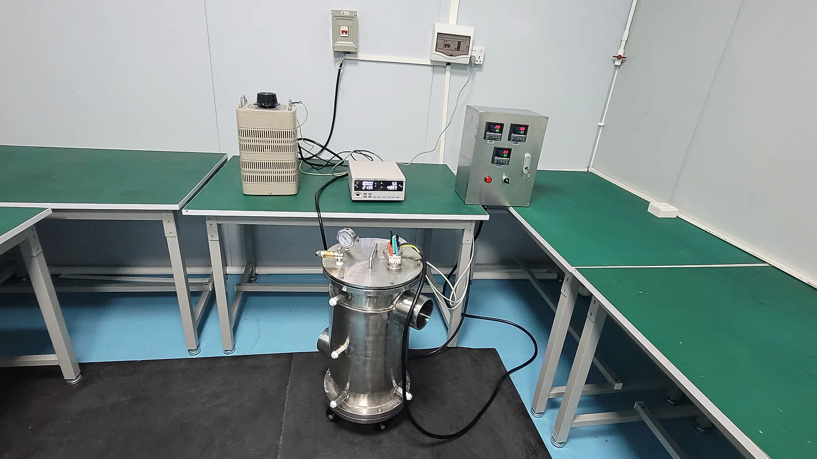
In a diagnostic or medical instrument, the heater is part of a controlled thermal system rather than an isolated wattage value. Sample geometry, heat losses, sensor placement, control logic, cleaning exposure, insulation, fault handling, and the instrument risk file all affect the released design.
Printed heaters can support compact, shaped heat zones on ceramic or metal-based structures. Suitability depends on the complete temperature-control assembly and its regulatory context.
A printed heater may fit small reaction blocks, fluid paths, sensor chambers, or instrument surfaces where mounting space and warm-up behavior are tightly coupled.
Multiple zones or shaped resistance patterns can be reviewed when the target surface, allowed gradient, contact stack, airflow, and steady or cyclic duty are known.
Sensor location, thermal fuse or cutoff, controller limits, grounding, leakage, and safe-fault behavior should be designed with the heater rather than added later.
Detergents, disinfectants, reagents, condensation, and material declarations may affect terminals, protection layers, adhesives, seals, and the assembly process.
These application inputs help separate heater design from instrument-level safety and performance obligations.
| System requirement | Why it changes the circuit | What the project must define |
|---|---|---|
| Temperature profile | Sets heat-zone geometry, resistance distribution, sensing points, control bandwidth, warm-up strategy, and thermal margins. | Setpoint range, ramp and recovery time, uniformity map, overshoot limit, duty cycle, and ambient conditions. |
| Sample or fluid interface | Controls heat path, contact pressure, wetted boundary, thermal mass, local losses, and whether a removable carrier is involved. | Assembly section, materials, fluid flow or volume, contact stack, tolerances, and worst-case load. |
| Electrical safety | Influences dielectric stack, clearances, terminals, grounding, insulation monitoring, and protection components. | Supply type, working voltage, leakage and withstand criteria, applicable standard, grounding class, and fault conditions. |
| Cleaning and contamination | Affects protective layer, connector, sealing, adhesive, corrosion control, and inspection after exposure. | Agents, concentrations, temperature, method, frequency, residue limits, and material documentation. |
| Risk and traceability | May add lot records, controlled changes, inspection data, serialization, and validation evidence tied to the instrument file. | Device classification context, customer risk controls, required records, sampling plan, and approval route. |
A credible application page should make the surrounding interfaces visible. These are the places where otherwise reasonable component designs often fail during integration.
A heater component test can support development, but it does not certify a medical or diagnostic device. Acceptance criteria must come from the customer's risk-based instrument plan.
Check resistance, power, insulation, dielectric integrity, leakage where applicable, and sensor correlation before thermal cycling.
Expected outputBaseline electrical record under defined ambient conditions.
Measure warm-up, overshoot, steady-state uniformity, recovery, and control stability in a production-intent thermal stack.
Expected outputTemperature map and time-domain response at nominal and worst-case loads.
Apply the released cleaning, reagent, humidity, condensation, storage, and temperature conditions.
Expected outputPre/post inspection with electrical, thermal, adhesion, or corrosion findings.
Evaluate sensor faults, no-load or dry conditions, power-control faults, cutoff behavior, and representative duty cycles.
Expected outputRisk-control evidence for integration into the customer's instrument validation.
Mark unknown values as “for application review.” The first response is more useful when the system interfaces and validation responsibility are visible from the start.
Upload drawings, a requirements file, or clear sample and assembly photos.
Short answers to scope questions that often block a useful quotation.
Only if the term is tied to defined requirements and supporting evidence for the actual project. A heater component by itself does not establish medical-device compliance or clinical suitability.
A sectioned assembly drawing plus the required temperature-versus-time profile is usually more useful than wattage alone. Include the load, contact stack, airflow or fluid condition, sensor location, and ambient extremes.
No. The page image is explicitly a generated application visualization. Product or project evidence must come from authorized drawings, samples, test records, and traceable production documents.