Custom motion-to-output curve
Rotary, arcuate, or linear geometry can be evaluated when the mechanical travel, electrical endpoints, dead zones, tolerance, and controller interpretation are supplied together.

Application engineering guide
Start with the mechanism, output curve, contact system, fluids, temperature, vibration, and vehicle-level validation—not a generic resistor-card specification.
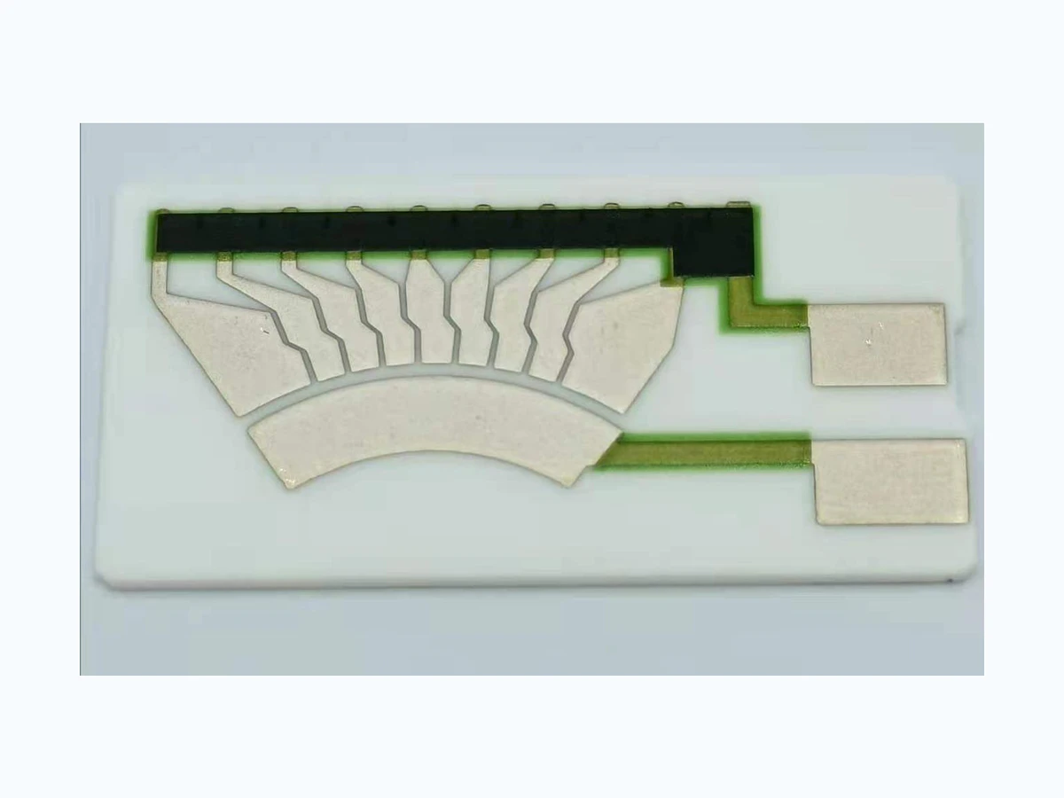
A printed resistive element is only one part of an automotive sensing system. The released curve depends on the track, wiper, linkage, connector, controller input, mounting stack, and operating environment working together. A useful review therefore begins with the complete sensing mechanism and the validation plan for the finished assembly.
A thick film or polymer-resistor route can be worth reviewing when the sensor needs a compact custom track or curve, but the substrate and process cannot be selected from the application name alone.
Rotary, arcuate, or linear geometry can be evaluated when the mechanical travel, electrical endpoints, dead zones, tolerance, and controller interpretation are supplied together.
Track material, conductor interface, protective regions, wiper geometry, force, speed, direction changes, and expected cycles must be treated as one tribological system.
Fuel, oil, vapor, condensation, cleaning residue, and housing materials can affect the track, terminals, seals, and insulation. Exact media and exposure conditions belong in the RFQ.
Ceramic and printed-resistor formats can reduce interconnects, but edge support, fasteners, connector load, shaft or float alignment, and service access still control the mechanical design.
The table turns system requirements into drawing and validation inputs. It is not a list of universal automotive capability limits.
| System requirement | Why it changes the circuit | What the project must define |
|---|---|---|
| Output function | Defines track topology, active angle or travel, end regions, segmentation, redundancy, and measurement points. | Target resistance-versus-position data, tolerances, supply and load circuit, sampling method, and calibration logic. |
| Contact system | Influences conductor overlap, wear path, surface protection, contact pressure, signal noise, and track support. | Wiper material and geometry, normal force, speed, dwell, reversal, allowable contact resistance, and cycle profile. |
| Fuel, oil, or vapor | Changes material compatibility, sealing, terminal protection, insulation, cleaning, and exposure-test planning. | Exact fluids and additives, temperature, immersion or vapor mode, duration, pressure, and acceptance checks. |
| Temperature and vibration | Affects substrate mounting, connector strain, resistance drift budget, housing expansion, and inspection after stress. | Operating and storage profiles, thermal cycling, vibration spectrum, mounting condition, and powered or unpowered state. |
| Safety and diagnostics | May require dual tracks, plausibility zones, open/short detection, controlled endpoints, or traceability in the assembly. | System architecture, diagnostic thresholds, fault response, applicable standards, and customer validation responsibility. |
A credible application page should make the surrounding interfaces visible. These are the places where otherwise reasonable component designs often fail during integration.
Component measurements should connect to mechanism and system behavior. Vehicle- or equipment-level qualification remains the customer's program-specific responsibility.
Confirm outline, datums, track registration, terminals, resistance endpoints, and the released measurement setup.
Expected outputDimension report and baseline electrical or curve data.
Install the element in the production-intent sender or actuator and compare mechanical position with electrical output.
Expected outputPosition-to-output correlation, hysteresis, repeatability, and contact observations.
Apply the defined fluid, temperature, humidity, vibration, or thermal-cycle profile in the actual mounting condition.
Expected outputPre/post electrical comparison and visual or mechanical findings.
Run the released movement duty and evaluate signal noise, wear, endpoints, faults, and controller plausibility.
Expected outputCycle record, drift or wear review, and system diagnostic results.
Mark unknown values as “for application review.” The first response is more useful when the system interfaces and validation responsibility are visible from the start.
Upload drawings, a requirements file, or clear sample and assembly photos.
Short answers to scope questions that often block a useful quotation.
A sample can start the review, but an accurate release also needs measured travel or angle, endpoint definitions, controller loading, tolerance, wiper conditions, and the intended calibration method.
No. Track material matters, but wiper geometry and force, alignment, contamination, motion profile, housing support, electrical loading, and environmental exposure all influence system life.
No. It explains engineering inputs for automotive applications. Any required quality-system, material, validation, or customer-specific approval must be identified and verified for the actual program.