
Overview
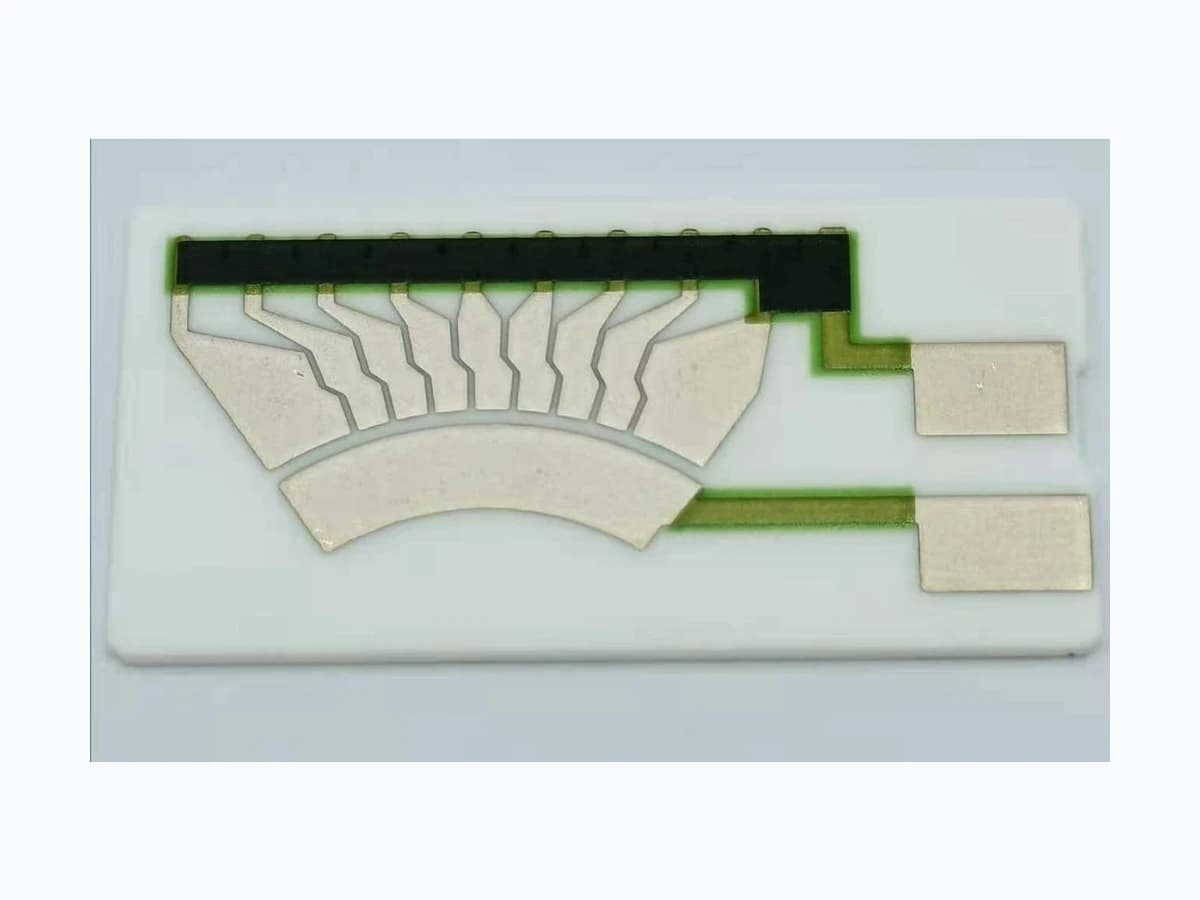
A fuel-level sender is a measurement chain, not an isolated resistor card. this guide shows how an OEM team can translate tank geometry and float motion into a controlled electrical curve, then define the contact, fuel, electronics, diagnostic, and assembly tests needed to judge the complete sender without assuming final-system performance.
Failure controls
These are review prompts, not evidence that every risk applies or that every test is available.
- A
A nominally correct resistor curve can indicate the wrong volume when tank geometry, installation attitude, or linkage travel differs from the design reference.
- B
Mechanical backlash, float interference, or stop variation can create hysteresis that electrical trimming cannot remove.
- C
An undefined mating wiper or contact load can cause noise, intermittent output, accelerated wear, or damage to the resistive path.
- D
Fuel composition, additives, condensation, or contamination can change exposed interfaces and must not be covered by a generic fluid-resistance claim.
- E
Controller loading, filtering, and diagnostic thresholds can distort or reject an otherwise acceptable raw sender output.
- F
Valid endpoint saturation can be mistaken for an electrical fault unless mechanical limits and diagnostic regions are coordinated.
- G
A tolerance stack closed only at nominal empty and full positions can miss a large intermediate indication error caused by tank contour, arm geometry, track segmentation, or controller interpolation.
Engineering review matrix
Each row links a design variable to evidence that can support a drawing or release decision.
| Variable | Control question | Verification route |
|---|---|---|
| Tank geometry and level datum | Which tank orientation, usable-volume definition, reserve zone, baffle condition, and reference levels govern the requested indication? | Correlate known fill volumes or controlled level positions with the sender datum in the representative tank geometry. |
| Float and linkage kinematics | How do float buoyancy, arm geometry, pivot, stops, clearances, and tolerance accumulation convert liquid level into wiper travel? | Record position at defined level points in both travel directions and compare the measured motion with the released linkage model. |
| Resistance curve and endpoints | Are curve direction, breakpoint table, endpoint values, dead zones, interpolation rule, and tolerances defined at stated reference conditions? | Measure a full forward and reverse electrical sweep and calculate error at every released breakpoint, including both endpoints. |
| Wiper contact interface | What mating contact, normal force, path, speed, surface condition, debris risk, and interruption limit belong to the sender design? | Evaluate contact variation, discontinuity, wear pattern, and repeatability with the specified mating wiper and motion profile. |
| Fuel and environmental exposure | Which identified fuel, additives, temperature cycles, humidity, vibration, storage, and contamination conditions contact the card or sender assembly? | The OEM or its qualified validation owner should condition representative assemblies under the agreed exposure sequence and compare electrical, contact, and visual results before and after exposure. |
| Electronics interface | What excitation, pull-up or pull-down network, input impedance, sampling, filtering, grounding, and connector arrangement loads the sender? | The system owner should test the sender with the intended controller interface or a documented electrical equivalent across valid and diagnostic states. |
| Fault and plausibility logic | Which opens, shorts, stuck positions, intermittent contacts, channel conflicts, or out-of-range values must be detected by the vehicle system? | The OEM or designated system-validation owner should inject each agreed fault at the assembly interface and record detection threshold, response, recovery, and any ambiguous state. |
| Calibration and acceptance | Is acceptance based on resistance, voltage, indicated volume, percentage level, or another output, and at which mechanical and environmental conditions? | Use one controlled correlation table linking physical level, mechanism position, raw electrical value, interpreted output, uncertainty, and disposition. |
Sender transfer-chain definition
The order makes assumptions and ownership visible before a result is promoted to a requirement.
- 01
Fix the tank reference frame
Define usable volume, installation attitude, baffles, reserve region, pickup constraints, datum surfaces, and the level points the vehicle system must distinguish before assigning an electrical curve.
- 02
Translate level into wiper travel
Map float buoyancy, arm length, pivot position, mechanical stops, clearances, and tolerance stack to the actual angular or linear travel available on the resistive track.
- 03
Allocate the electrical response
Specify curve points, endpoint behavior, direction, resistance or ratio output, permitted interpolation error, and reference conditions in a table tied to mechanical positions rather than a sketch alone.
- 04
Define contact and diagnostic states
Coordinate wiper load and path with excitation, input impedance, filtering, open- and short-circuit detection, damping, and the controller response to values outside the valid travel range.
- 05
Correlate the assembled sender
Measure forward and reverse level sweeps in the representative tank assembly, compare mechanical position and electrical output, and retain deviations, test conditions, revision, and disposition in the validation record.
- 06
Close the tolerance and uncertainty budget
Combine tank and fill-reference uncertainty, float buoyancy, pivot and arm variation, wiper alignment, printed-curve variation, contact contribution, harness resistance, controller conversion, temperature, and test-fixture uncertainty at every required indication point. Evaluate forward and reverse travel separately, identify which contributor dominates each region, and assign an owner for every guard band. The released table should distinguish design allowance, manufacturing acceptance, calibration allowance, measurement uncertainty, and residual system error so that one generous endpoint tolerance cannot conceal a weak reserve or mid-volume region.
Reference boundary
Public method sources
These sources support the engineering method and terminology used in this technical guide. They do not establish a ThickFilmPCB material list, capability limit, customer result, certification, or finished-product specification.
- 01SAE 921450 — Reliable Measurement of Fuel Level
Supports treating the float, arm, moving contact, resistor, tank, and vehicle indication as one sender measurement chain.
- 02SAE 2002-01-1074 — Design Guidelines for Automotive Fuel Level Sensors
Supports reviewing fuel exposure, track and contact choices, noise, wear, and failure modes at the sender-design level.
- 03SAE 2016-01-1379 — Fuel Slosh Effects on Fuel-Level Sensors
Supports evaluating tank geometry, baffles, vehicle motion, and float response together, with simulation correlated to vehicle testing.
Inputs for a practical review
Unknown values may be labelled unknown. The review should convert uncertainty into an explicit decision or validation task.
Send Drawings- 01
Tank drawing or section with installation attitude, usable volume, baffles, reserve region, datum, and sender mounting interface
- 02
Float, arm, pivot, stop, and wiper geometry with available travel and tolerance information
- 03
Target level-to-resistance, ratio, or voltage table including endpoints, direction, tolerances, and reference conditions
- 04
Mating wiper material or specification, contact force, motion rate, expected cycles, and permitted interruption or noise
- 05
Fuel or fluid identity, additives, temperature, vibration, humidity, storage, and contamination exposure profile
- 06
Controller excitation, input network, filtering, connector pinout, diagnostic thresholds, and fault response
- 07
Prototype quantity, drawing revision, assembly ownership, validation matrix, and required records