
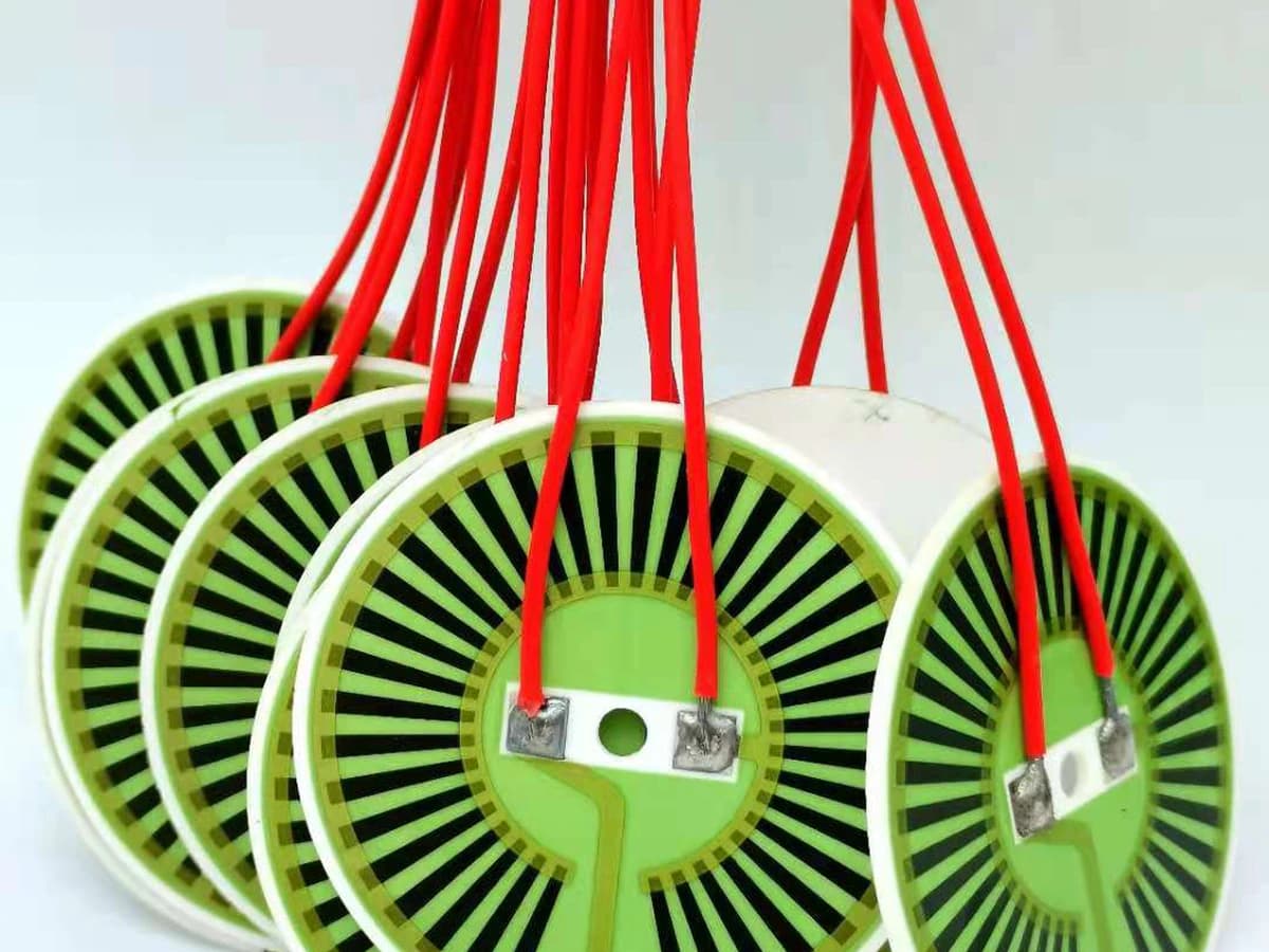
Overview
Heater trace geometry translates an electrical target into a printable and thermally useful resistor pattern. Width, length, spacing, turns, conductor overlaps, edge clearances, local heat sinking, and paste selection act together; none can be released from a single nominal line width. A sound design starts with the complete electrical and thermal boundary, estimates resistance from sheet resistance and aspect ratio, maps local power, then reserves enough process margin for printing, firing, trimming, protection, mounting, and inspection. The result remains a drawing-specific hypothesis until a production-intent stack is measured in its real assembly.
Engineering review matrix
Each row links a design variable to evidence that can support a drawing or release decision.
| Variable | Control question | Verification route |
|---|---|---|
| Electrical target and supply | Define cold resistance, reference temperature, supply range, current limit, control waveform, duty, leakage, and transient states without inferring a surface temperature from watts alone. | Measure voltage, current, resistance, and waveform at defined states using the actual leads and controller, with instrument uncertainty recorded. |
| Fired sheet resistance and thickness | Name the material system, applicable resistance decade, lot control, print thickness, firing profile, refire history, conductor interaction, and any trim or protection sequence. | Use drawing-linked coupons or representative patterns and correlate fired thickness, geometry, and resistance across position and lot. |
| Width, gap, and registration | Dimension finished line width, spacing, pitch, turn radii, overlap, datum, and tolerances based on the selected printing route and full layer stack. | Inspect fired critical features at the agreed magnification and sampling plan; record bridges, opens, edge quality, and registration rather than accepting a nominal artwork file. |
| Local heat boundary | Map contact area, pressure, interface material, load conductivity, flow, convection, insulation, holes, fasteners, and thermal sinks on both faces and around the perimeter. | Compare a documented model with time-resolved measurements at fixed, drawing-referenced locations in the actual assembly. |
| Terminal transition | Define conductor overlap, terminal geometry, joint route, lead gauge, strain relief, current path, local protection, and heat sinking without assuming the resistor trace can simply end at a pad. | Measure voltage drop and temperature at the transition and inspect joint, metallization, and nearby resistor condition before and after cycling. |
| Electrical separation | Set gaps, edge distance, openings, dielectric coverage, contamination assumptions, working and transient voltage, ground, accessible metal, and application-standard boundary. | Review the complete section and use the project-selected insulation, leakage, and withstand methods on the production-intent stack. |
| Tolerance and change control | Allocate artwork, screen, print, firing, material, trim, substrate, assembly, and measurement variation; identify which changes require a new model or qualification. | Use nominal and tolerance-biased samples, statistical evidence where available, and configuration-linked records before freezing limits. |
Controlled model
Trace geometry, resistance, and local heating model
Use the model to organize a first design, not to declare a heater temperature. Define the paste system, fired geometry, resistance reference condition, supply tolerance, mounting stack, heated load, convection, radiation, sensor position, and fault states before comparing patterns. Printed corners, conductor overlaps, trim features, and thickness variation require correction or test beyond the ideal rectangular-strip equations.
R₀ ≈ Rₛ (L / W)Estimates the cold resistance of a uniform printed resistor from sheet resistance and the number of squares.
- Units
- R₀ and Rₛ in Ω; L and W in the same length unit
- Use boundary
- Applies to an approximately uniform fired film away from turns and terminations. Use effective fired dimensions and include contact, corner, thickness, and material-lot effects separately.
P = V² / R(T) = I² R(T)Relates electrical input to voltage, current, and the heater resistance at the defined temperature state.
- Units
- P in W; V in V; I in A; R in Ω
- Use boundary
- This is electrical input, not heat delivered to the load. Resistance may vary with temperature, and supply control, leads, terminals, and losses must be included.
q''_e = P_segment / A_segmentScreens local electrical power per printed area for a named trace segment.
- Units
- q'' in W/m² or W/mm² when consistently stated
- Use boundary
- Printed-area loading is not the same as heat flux into the product. Substrate spreading, interfaces, edge losses, thermal mass, and fluid conditions determine the temperature field.
Decision comparison
| Decision | Route A | Route B | Verification |
|---|---|---|---|
| Narrower, longer trace | Raises square count within a fixed region and can help reach resistance, but increases sensitivity to width variation, defects, trim damage, and local current crowding. | A wider path reduces dimensional sensitivity and current density but may require more length, another resistance decade, or a different topology to reach the target. | Measure fired geometry and resistance across representative locations, then correlate infrared or contact temperature maps under the released mounting and supply conditions. |
| Dense spacing versus thermal spreading | Closely packed lanes can distribute electrical input over an area when printing and electrical separation remain controlled. | More open spacing may reduce print-bridging risk and allow routing around holes or terminals, but the substrate must spread heat across the larger cold regions. | Inspect fired gaps at the agreed magnification and compare temperature uniformity, hot spots, leakage, and abnormal-condition response on production-intent samples. |
| Uniform pitch versus locally shaped pitch | A uniform serpentine is easier to dimension and inspect but may overheat thermally isolated edges or underheat strongly coupled load zones. | Locally changed width or pitch can compensate for a known heat boundary, yet every transition becomes a current-density and process-tolerance review point. | Use a mapped load boundary, a documented model, and measured temperature fields at nominal and tolerance extremes rather than visual symmetry alone. |
- A process firing temperature, when stated in a controlled material document, is not a heater operating-temperature rating.
- A visually even serpentine does not establish a uniform temperature because heat removal, mounting pressure, airflow, fluid contact, holes, edges, and terminals can dominate the field.
Trace-layout review sequence
The order makes assumptions and ownership visible before a result is promoted to a requirement.
- 01
Freeze the system boundary
Record supply minimum and maximum, control method, target heat at the load, allowable temperature field, warm-up, steady duty, cycling, ambient, mounting, interfaces, sensors, and fault states. Separate electrical input from useful heat and state which organization owns safety and final application qualification.
- 02
Allocate resistance and area
Translate the cold and hot resistance requirements into a bounded square-count range using controlled material inputs. Reserve the actual available print area after holes, edge clearance, terminals, attachments, inspection zones, and protection margins are removed rather than routing through the gross substrate outline.
- 03
Construct manufacturable geometry
Choose lane width, gap, pitch, turn style, transitions, conductor overlaps, trim allowance, fiducials, and registration strategy. Include expected fired dimensions and tolerances; avoid isolated necks, acute inside corners, tiny islands, abrupt width steps, and ambiguous inspection datums.
- 04
Model the coupled thermal field
Assign segment power to the production-intent substrate, dielectric or protective layers, joints, contact material, heated load, insulation, convection, radiation, and neighboring structures. Evaluate nominal and tolerance cases, especially partial contact, edge cooling, terminal heat sinking, and loss of load.
- 05
Plan process and measurement controls
Define print screen, emulsion, paste conditioning, wet and fired thickness observations, registration, firing history, refires, resistance measurement temperature, probe locations, visual criteria, trim sequence, and traceability. Supplier typical values remain input evidence, not an outgoing acceptance result.
- 06
Prototype and close the loop
Build representative layouts, measure geometry and resistance before and after any trim or protection, instrument the real assembly, and run the agreed duty and fault matrix. Feed correlated results back into the drawing, model assumptions, tolerance allocation, control plan, and change rules before any release decision.
Failure controls
These are review prompts, not evidence that every risk applies or that every test is available.
- A
Selecting a nominal width from a generic printing table without accounting for fired geometry, paste behavior, corners, registration, and inspection method.
- B
Using total watts or average printed-area loading to claim a temperature while ignoring the real load, interfaces, losses, and control state.
- C
Creating narrow necks at turns, trim sites, terminal entries, or hole bypasses that carry disproportionate current and become local hot spots.
- D
Packing lanes so closely that normal print spread, registration error, contamination, or protection defects can create bridges or compromised separation.
- E
Optimizing a free-air sample and then changing contact pressure, housing, airflow, fluid, sensor position, or insulation in the qualified assembly.
- F
Treating a material supplier's firing condition or typical test coupon as a finished-heater operating rating or company capability claim.
Reference boundary
Public method sources
These sources support the engineering method and terminology used in this technical guide. They do not establish a ThickFilmPCB material list, capability limit, customer result, certification, or finished-product specification.
- 01Heraeus Electronics — Thick Film Heaters overview
Supports treating substrate, dielectric, conductor, resistor, processing, termination, control, and application boundary as a coupled heater system. The supplier overview does not establish a ChipSimple material, geometry, power density, operating temperature, or validation result.
- 02Heraeus Electronics — R900R thick-film resistor material page
Supports linking one named resistor material to its stated sheet-resistance options, processing conditions, fired properties, and test context only. Supplier data must not be transferred to another paste, geometry, stack, or company capability.
- 03NIST Technical Note 1297 — measurement uncertainty
Supports identifying and reporting measurement-uncertainty components when correlating resistance, dimensions, electrical input, and temperature data; it provides no heater design limit or performance rating.
Inputs for a practical review
Unknown values may be labelled unknown. The review should convert uncertainty into an explicit decision or validation task.
Send Drawings- 01
Dimensioned outline and layer artwork with holes, keep-outs, trace width and gap intent, terminal zones, datums, tolerances, and critical inspection features.
- 02
Supply range, controller and waveform, cold-resistance reference, power or heat-at-load target, current limits, duty cycle, transients, and fault cases.
- 03
Required temperature field, warm-up and steady limits, sensor type and location, allowable gradients, and measurement or acceptance method.
- 04
Substrate, printed material, conductor, dielectric or protective stack requirements, firing or curing restrictions, refires, and approved substitutions.
- 05
Complete mounting and heat-transfer stack including contact area, interface materials, pressure, fasteners, fluid or airflow, insulation, enclosure, and heated load.
- 06
Terminal construction, leads, connectors, joining route, strain relief, assembly heat history, grounding, and accessible-metal requirements.
- 07
Prototype matrix, validation duties, abnormal states, inspection sampling, traceability, reports, change control, quantity, and drawing revision.