
THICK FILM ENGINEERING LIBRARY

Technical guide · Global English edition

TFC / CALCULATOR / SHEET RESISTANCE CALCULATOR

Sheet resistance from a uniform test strip

Document type
Calculator
Updated
3 September 2026
Use
Engineering reference

Abstract

For a uniform rectangular film with full-width equipotential contacts, the number of squares is length ÷ width and sheet resistance is measured resistance ÷ squares. The calculator keeps the geometry and assumptions visible.

Index termsengineering calculatorbounded estimatedesign intake
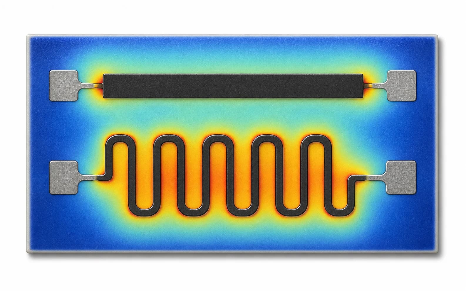
Engineering illustration of a uniform printed resistor strip beside a serpentine trace
Fig. 1The calculator treats the printed strip as a uniform number of squares; real results remain dependent on geometry, terminals and measurement condition.Conceptual illustration · not measurement evidence

Technical worksheet

Calculation and intake panel

Local browser calculation · no project data is uploaded

Calculated uniform-strip result

50 Ω/□

2 squares · Rs = R × W/L

Use the worksheet with your drawing

Sheet resistance, geometry and independent worst-case bounds. Includes assumptions and a clearly marked arithmetic example.

Download XLSX

Excel-compatible .xlsx · revision 9 September 2026. Inputs stay in your file. Estimates support engineering review and do not approve product performance.

Method boundaryDo not use this result for irregular geometry, narrow/contact-dominated patterns, nonuniform films, curved current paths, or final acceptance without an agreed measurement method.

Engineering question

What approximate sheet resistance is implied by this measured rectangular test pattern?

Equation and assumptions

Squares N = L/W. Sheet resistance Rs = R/N = R × W/L. Length and width may use any common unit because their ratio is dimensionless; measured resistance is entered in ohms and the result is ohms per square.

  • Uniform film thickness and material
  • Rectangular active region
  • Length measured between the effective contact boundaries
  • Contacts span the width and contact/lead resistance is negligible or corrected
  • Measurement conditions and temperature are recorded

Published test vectors

Calculator test vectors
ResistanceLengthWidthExpected squaresExpected sheet resistance
100 Ω20 mm10 mm250 Ω/□
250 Ω10 mm10 mm1250 Ω/□
80 Ω5 mm10 mm0.5160 Ω/□

Carry the result into a real review

  • Material/paste identity and lot
  • Substrate and surface condition
  • Printed, dried and fired/cured process state
  • Active geometry and contact construction
  • Instrument, connection, temperature and measurement direction
  • Repeat locations, variation and acceptance rule

Engineering navigation

Related engineering guides

Continue from the next relevant design or verification decision.
  1. 01
    Thick film resistor design

    Use sheet resistance inside a complete geometry and tolerance review.

  2. 02
    Silver paste guide

    See why a conductor value belongs to a named material/process context.

  3. 03
    Technology Center

    Start from the full material, process, and design map.

  4. 04
    Send drawings

    Request an application-specific engineering review.

Method sources and scope

External sources support the stated engineering method only. Supplier data is not a ThickFilmPCB material, capability or finished-product specification.

  1. NIST thick-film terminology technical notePrimary government reference defining sheet resistivity as the resistance of a uniform sheet measured across a unit square, expressed in ohms per square.

Thick Film Engineering Library · Technical guide · Updated 3 September 2026