Signal conditioning close to the sensor
Printed resistors or ceramic interconnect can be reviewed where size, temperature behavior, calibration access, or reduced interconnect is important.

Application engineering guide
Define the measurand, signal chain, process connection, enclosure, calibration, contamination, and field duty before selecting a ceramic circuit route.
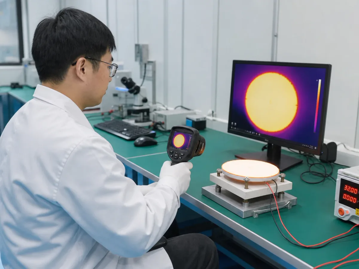
Industrial instruments combine a sensing element, signal conditioning, process connection, enclosure, power and communications interface, and calibration method. A ceramic or printed-resistor circuit should be reviewed against that full chain, especially where temperature, contamination, isolation, or compact packaging drives the design.
The application may need a resistor function, a stable interconnect platform, a heater, or a compact hybrid interface. Those functions lead to different material and process choices.
Printed resistors or ceramic interconnect can be reviewed where size, temperature behavior, calibration access, or reduced interconnect is important.
Custom resistive tracks may fit floats, valves, slides, actuators, and rotary mechanisms after the motion conversion and contact system are defined.
Heaters may support condensation control, sample conditioning, or stable measurement zones when the control and fault strategy are part of the system design.
Ceramic platforms may be useful near heat, vibration, or contamination, but connectors, seals, coatings, mounting stress, and process media often dominate field reliability.
Begin with the instrument function and the process boundary. Avoid treating a generic high-temperature claim as a substitute for assembly-level review.
| System requirement | Why it changes the circuit | What the project must define |
|---|---|---|
| Measurand and signal chain | Determines resistor topology, signal level, loading, calibration access, shielding, grounding, and noise sensitivity. | Sensor output, excitation, input impedance, accuracy budget, response time, filtering, and calibration method. |
| Process media | Affects isolation diaphragm or barrier, seals, terminals, coating, cleaning, and condensation management. | Media chemistry, pressure, flow, particulates, humidity, cleaning, temperature, and contact boundary. |
| Enclosure and mounting | Controls board support, connector load, stress transfer, thermal path, serviceability, and ingress protection strategy. | Sectioned housing, fasteners, datums, cable glands, potting or coating, and assembly torque. |
| Field electrical environment | Influences isolation, clearances, transient protection interfaces, grounding, and test accessibility. | Supply, communications, common-mode conditions, transients, EMC plan, and safety requirements. |
| Calibration and maintenance | May require trim access, stored coefficients, test pads, replaceable modules, traceability, and stable fixtures. | Calibration points, accuracy and drift limits, environmental compensation, interval, and service model. |
A credible application page should make the surrounding interfaces visible. These are the places where otherwise reasonable component designs often fail during integration.
A useful plan links circuit checks to transmitter or actuator behavior under the released mounting and process conditions.
Verify geometry, printed features, continuity, resistor values, attachment interfaces, and assembly-induced stress.
Expected outputBaseline dimensional and electrical record.
Compare input measurand with circuit and instrument output across the required range and temperature points.
Expected outputError, repeatability, hysteresis, and compensation data.
Apply the defined temperature, humidity, vibration, contamination, power, and electrical disturbance conditions at system level.
Expected outputPre/during/post functional data and inspection findings.
Exercise the expected operating cycles, calibration interval, connector handling, and service or replacement procedure.
Expected outputDrift, wear, serviceability, and change-control evidence.
Mark unknown values as “for application review.” The first response is more useful when the system interfaces and validation responsibility are visible from the start.
Upload drawings, a requirements file, or clear sample and assembly photos.
Short answers to scope questions that often block a useful quotation.
No. Ceramic can help with specific thermal, dimensional, or insulation needs, but the complete assembly—including seals, connectors, mounting stress, coatings, process media, and enclosure—determines suitability.
Provide the input range, reference points, temperature points, accuracy and drift budget, loading, measurement fixture, coefficient handling, and production acceptance method.
A photo helps identify packaging, but route selection still needs the circuit function, dimensions, signals, assembly interfaces, environment, tests, quantities, and preferably a drawing or sample.