
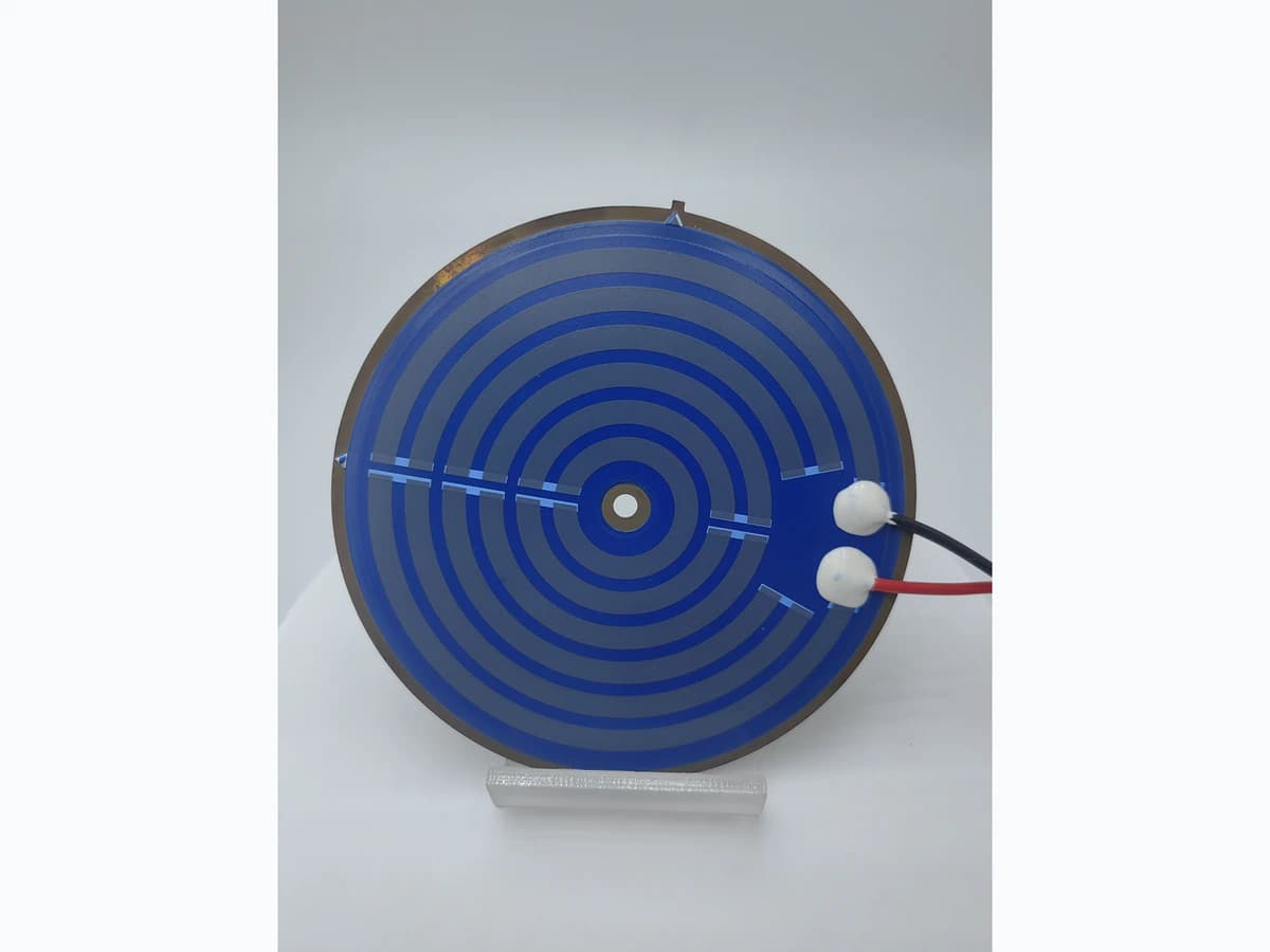
Overview
Dry operation and mineral scale are system heat-transfer risks, not properties a heater element can solve alone. this guide helps an OEM define abnormal thermal states, sensing locations, control response, independent protection, water or fluid conditions, and assembly-level tests without implying a universal safe power, trip temperature, or protection lifetime. IEC 60335-2-15 is included only as one household-and-similar liquid-heating appliance example; the actual end-equipment scope and applicable standard must be selected before using the method.
Failure controls
These are review prompts, not evidence that every risk applies or that every test is available.
- A
A sensor remote from the emerging hot spot can report an acceptable temperature after the heater interface has already overheated.
- B
Scale or fouling can be treated as a localized thermal-resistance risk, but its location, composition, progression, and severity must be justified for the named fluid and appliance rather than transferred from a generic deposit assumption.
- C
One dry-run test does not cover partial wetting, trapped gas, low flow, repeated restart, sensor detachment, or progressive fouling.
- D
Thresholds copied between assemblies can fail because thermal mass, mounting, fluid path, supply, sensing lag, and control timing differ.
- E
Automatic reset can produce repeated overheating when the underlying loss of heat transfer remains present.
- F
A protective trip does not by itself prove that insulation, attachment, conductor, resistor, seal, or adjacent material remains fit for further service.
Abnormal heat-transfer protection sequence
The order makes assumptions and ownership visible before a result is promoted to a requirement.
- 01
Define normal heat rejection
Document fluid coverage, flow, fill sequence, mounting contact, ambient losses, duty cycle, supply tolerance, and the normal temperature-time envelope at the heater, sensor, and protected assembly.
- 02
Describe credible degraded states
Separate empty operation, partial wetting, trapped air, low flow, blocked flow, scale growth, poor mounting contact, sensor detachment, and control failure because each produces a different thermal signature.
- 03
Place sensing against the failure
Choose temperature, rate-of-rise, current, flow, level, pressure, or combined signals according to where and how quickly each fault becomes observable, including sensor tolerance and lag.
- 04
Allocate control and independent protection
Define detection thresholds, debounce, power reduction, shutoff, latching, reset, fault reporting, and any independent protective device without assuming that software alone covers every single fault.
- 05
Validate progressive and abrupt faults
The equipment developer or its qualified validation owner should test representative assemblies from normal operation through abrupt dry-run and progressive scale or flow restriction, recording the hottest relevant location, detection time, response, recovery, and post-test condition.
Engineering review matrix
Each row links a design variable to evidence that can support a drawing or release decision.
| Variable | Control question | Verification route |
|---|---|---|
| Normal thermal boundary | What fluid coverage, flow, mounting, ambient, duty, inlet condition, and heat load define acceptable operation? | Map temperature and electrical behavior at agreed locations across the normal operating envelope and supply tolerance. |
| Heater electrical input | Which voltage states, resistance tolerance, power control method, switching behavior, and duty cycle can occur during normal and fault operation? | Capture voltage, current, resistance, commanded duty, and delivered power during each validation state. |
| Dry-run scenario | Does dry-run mean fully empty, partial wetting, loss of prime, trapped gas, interrupted flow, or another defined condition? | Reproduce each credible state with controlled initial conditions and measure the thermal signature before and after protective action. |
| Scale and fouling state | Which fluid chemistry, deposit location, thickness progression, surface coverage, and service interval represent the risk assessment? | The equipment developer should define and justify a documented representative deposit or controlled thermal-resistance method, then compare heat-up, hot-spot location, and control response over progression. Until that method is approved, scale location and severity remain validation hypotheses rather than product claims. |
| Sensor location and dynamics | Can the selected sensor see the earliest damaging condition, and what tolerance, attachment, response time, drift, and failure mode apply? | Compare sensor output with independent temperature measurements at risk locations during fast and slow fault development. |
| Control response | What threshold, rate logic, filtering, timing, power reduction, shutoff, latch, reset, and diagnostic behavior are required? | Inject boundary values and sensor faults to confirm deterministic response, including restart and loss-of-power behavior. |
| Independent protective path | Which single faults require a separate limiter, cut-out, fuse, flow interlock, level interlock, or other protection selected by the OEM safety process? | The equipment developer or qualified safety-validation owner should open or disable the primary control path and verify the independent path under its specified construction and fault conditions. |
| Post-fault integrity | Which insulation, leakage, resistance, attachment, deformation, surface, and restart criteria apply after protective operation? | Inspect and electrically evaluate the representative heater assembly after each fault exposure before allowing any reset or continued-use conclusion. |
Reference boundary
Public method sources
These sources support the engineering method and terminology used in this technical guide. They do not establish a ThickFilmPCB material list, capability limit, customer result, certification, or finished-product specification.
- 01IEC 60335-2-15:2024 — Appliances for Heating Liquids
Applies to household and similar liquid-heating appliances rated not more than 250 V. It excludes, among other categories, storage and instantaneous water heaters, medical appliances, exclusively industrial appliances, and corrosive or explosive locations; those applications require their own equipment standards.
- 02IEC 60730-1:2022 — Automatic Electrical Controls
Applies to automatic electrical controls used in or with household and similar equipment and supports control construction, operation, testing, and safety-related operating values, timing, and sequences. It does not establish a heater assembly's dry-run or scale performance.
- 03IEC 60730-2-9:2026 — Temperature-Sensing Controls
Applies to defined temperature-sensing controls and makes response dependent on construction and mounting. Where mounting affects a protective response value, that value belongs to the applicable equipment standard or manufacturer determination; the standard does not provide a universal heater trip value.
Inputs for a practical review
Unknown values may be labelled unknown. The review should convert uncertainty into an explicit decision or validation task.
Send Drawings- 01
Heater drawing, material stack, mounting interface, wetted area, thermal contacts, insulation boundary, and sensor locations
- 02
Supply voltage and tolerance, resistance or power target, control method, duty cycle, switching, and startup sequence
- 03
Fluid identity, inlet condition, expected flow or fill states, water chemistry, scale or fouling assumptions, and service interval
- 04
Normal temperature-time limits at the heater, fluid, housing, seals, wiring, and other protected locations
- 05
Credible dry-run, partial-wet, blocked-flow, low-flow, sensor, relay, control, and restart fault definitions
- 06
Detection, power-reduction, shutdown, latching, reset, diagnostic, and independent-protection requirements
- 07
Assembly-level fault test matrix, instrumentation, acceptance criteria, post-fault checks, and safety-review ownership