
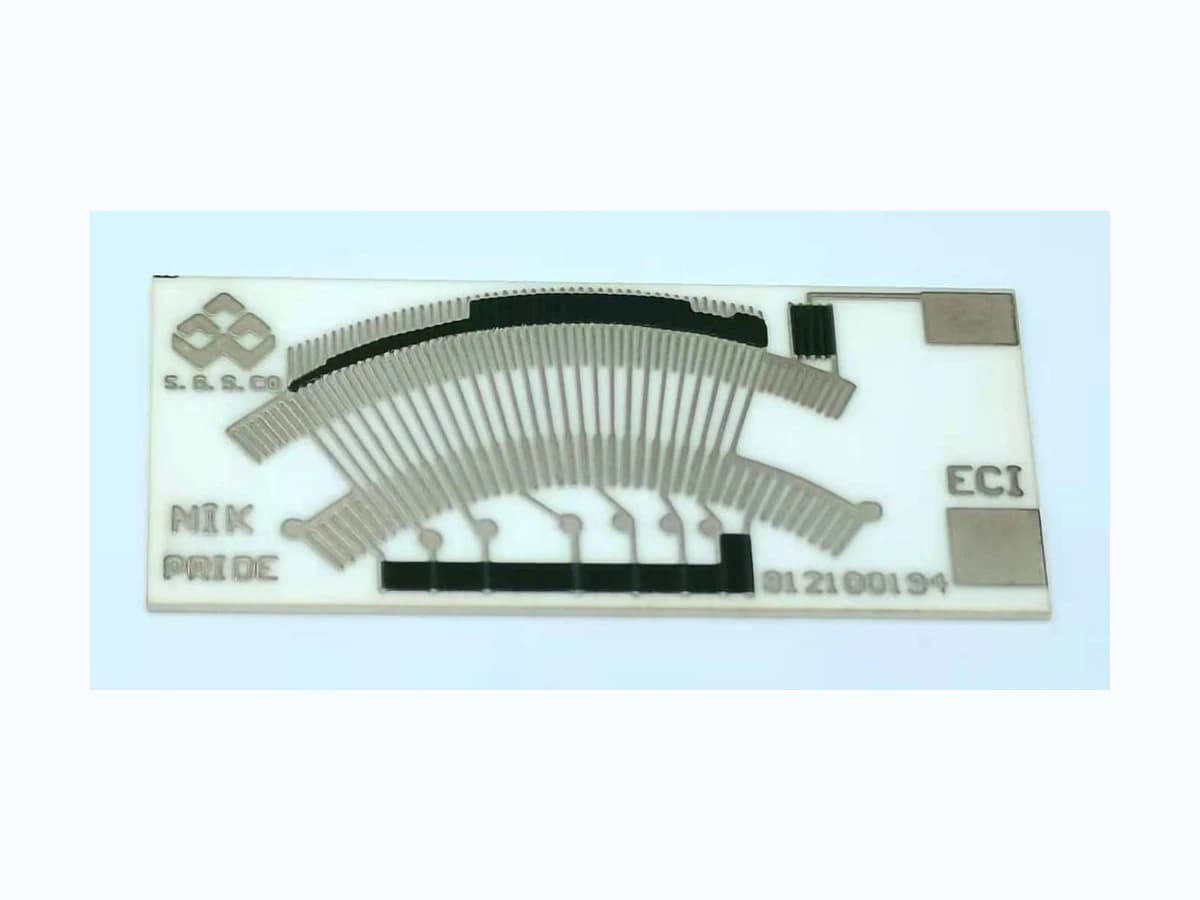
Overview
Industrial level sensing begins with the vessel, process fluid, installation, and control-system decision. this guide addresses a mechanical, continuous resistive-feedback route: it defines how those conditions drive motion conversion, resistive output, sealing or isolation, wiring, diagnostics, calibration, and maintenance without claiming suitability for a point-level function, a non-contact technology, a hazardous location, or a finished instrument.
Failure controls
These are review prompts, not evidence that every risk applies or that every test is available.
- A
A level-to-volume relationship can be nonlinear or installation-specific even when the electrical track itself is linear.
- B
Foam, turbulence, density change, deposits, or solids can move or obstruct a float independently of true process level.
- C
A suitable resistive element does not establish pressure containment, sealing, hazardous-location approval, or finished-instrument compliance.
- D
Ground offsets, long cables, moisture, connector resistance, and controller loading can change the interpreted signal.
- E
A calibration fixture that omits vessel geometry or mechanism loading can hide installed-system error.
- F
Cleaning or maintenance can alter linkage position, seal condition, wiper alignment, or calibration if service references are not controlled.
Engineering review matrix
Each row links a design variable to evidence that can support a drawing or release decision.
| Variable | Control question | Verification route |
|---|---|---|
| Measurement function | Is the output used for indication, process control, inventory, alarm, shutdown, or another task, and what failure consequence follows? | Trace every required level point and fault state through the raw sensor signal to the control-system action and acceptance criterion. |
| Vessel geometry and installation | Which datum, cross-section, mounting position, nozzle, baffle, wall clearance, tilt, and service access shape the available level-to-motion relationship? | Verify mechanism clearance and output at controlled levels in the representative vessel or a geometrically justified fixture. |
| Process fluid | What fluid identity, density, viscosity, conductivity, solids, foam, coating, corrosion, cleaning, pressure, and temperature states are relevant? | The process-equipment owner or its qualified validation owner should condition representative wetted or isolated interfaces using documented media and inspect function before, during, and after agreed exposures. |
| Motion mechanism | How do buoyancy, friction, linkage, shaft, stops, magnetic coupling, turbulence, deposits, and tolerance stack affect travel and repeatability? | Record forward and reverse motion, hysteresis, sticking, endpoint margin, and repeatability under representative process and mounting states. |
| Electrical transfer function | Are output direction, curve table, endpoints, tolerance, excitation, loading, and reference conditions defined for the controller interface? | Measure the full transfer curve under the intended electrical load and calculate error at each released process point. |
| Sealing, isolation, and enclosure | Which barrier separates process media from the resistive element, wiring, or electronics, and who owns its pressure, ingress, and material compatibility validation? | The equipment owner or qualified assembly-validation provider should test the specified assembled boundary using the OEM-defined pressure, ingress, media, thermal, and mechanical conditions. |
| Diagnostics and maintenance | How are open, short, stuck, intermittent, drifted, obstructed, or disconnected states recognized, and what inspection or calibration interval applies? | The control-system owner should inject electrical faults and controlled mechanical restrictions, then verify detection, annunciation, the specified control response, and recovery documentation. A safe-state claim applies only where the level function is formally allocated within a safety lifecycle. |
Process-vessel sensing definition
The order makes assumptions and ownership visible before a result is promoted to a requirement.
- 01
Define the process measurement
State whether the required function is point level, continuous level, usable volume, interface level, or another process variable. Continue with this resistive motion-to-signal method only for a compatible continuous mechanical route; point-level and non-contact functions require a separate sensing architecture and validation plan.
- 02
Characterize vessel and fluid
Document vessel geometry, datum, mounting, pressure, temperature, density, viscosity, conductivity, coating tendency, agitation, foam, vapor, contamination, cleaning, and access constraints.
- 03
Select the mechanical conversion
For the selected mechanical route, resolve how a float, linkage, shaft, magnetic coupling, or other actuator converts process level into repeatable travel. A direct wiper and a magnetically coupled position element have different media and contact boundaries and should not share an assumed validation chain.
- 04
Define signal and installation interfaces
Specify resistive or ratio output, excitation, wiring, grounding, connector, enclosure, sealing or isolation, controller input, filtering, fault regions, and any hazardous-location boundary owned elsewhere.
- 05
Plan calibration and maintainability
Correlate known levels with output in the installed geometry, then define inspection, cleaning, recalibration, fault checks, replacement references, and records needed to keep the measurement traceable.
Reference boundary
Public method sources
These sources support the engineering method and terminology used in this technical guide. They do not establish a ThickFilmPCB material list, capability limit, customer result, certification, or finished-product specification.
- 01IEC 61298-2:2026 — Process Instrument Tests Under Reference Conditions
Provides general methods for functional and performance tests of process instrumentation under reference conditions, except process measurement transmitters covered by the IEC 62828 series. It can support transfer-function reporting but not the page's environmental, media, pressure, or installation claims by itself.
- 02IEC 61511-1:2016+A1:2017 — Process-Industry Safety Instrumented Systems
Applies only where the level signal is part of a process-industry safety instrumented system; in that case, any safe-state function belongs to the complete SIS specification, design, installation, operation, and maintenance lifecycle.
- 03OSHA 29 CFR 1910.307 — Hazardous Locations
A United States workplace requirement that applies only to hazardous-classified locations. It assigns classification and approval to the documented area, equipment, wiring, installation, and specific material hazard—not to a resistor card in isolation—and does not replace the international or local scheme selected for another market.
Inputs for a practical review
Unknown values may be labelled unknown. The review should convert uncertainty into an explicit decision or validation task.
Send Drawings- 01
Measurement purpose, controlled variable, alarm or shutdown points, required output, and failure consequence
- 02
Vessel drawing with datum, geometry, mounting, baffles, nozzles, wall clearances, orientation, and service access
- 03
Named process fluid and ranges for density, viscosity, temperature, pressure, solids, foam, coating, corrosion, and cleaning
- 04
Float, linkage, shaft, coupling, wiper, travel, stops, sealing, enclosure, cable, and connector definition
- 05
Target level-to-resistance, ratio, or voltage table with endpoints, tolerance, direction, and reference conditions
- 06
Excitation, controller input, grounding, cable length, filtering, diagnostic limits, alarm logic, and fault response
- 07
Calibration method, representative fixture or vessel, exposure tests, maintenance plan, reporting, and approval ownership