
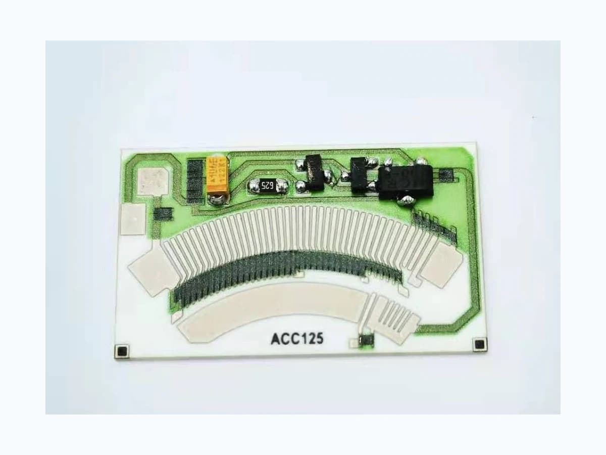
Overview
For a contact-based resistive feedback route, position is credible only when valve travel, actuator mechanics, the resistive track, controller loading, and diagnostic behavior are evaluated as one chain. Pneumatic intelligent positioners, electrically operated actuators, linear mounting interfaces, and rotary sensor cards have different standard and validation boundaries. this guide organizes those interfaces for industrial OEM review without claiming a finished actuator, functional-safety level, environmental rating, or field performance.
Failure controls
These are review prompts, not evidence that every risk applies or that every test is available.
- A
A feedback element can be electrically linear while gear backlash or linkage compliance makes actual valve position nonlinear and hysteretic.
- B
Using commanded actuator position as the validation reference can conceal a lost coupling, stalled valve, or slipping transmission.
- C
Contact interruption may be filtered out during steady bench testing but appear during vibration, direction reversal, or slow boundary movement.
- D
Redundant tracks do not provide diagnostic value unless their relationship, common-cause faults, wiring, and controller logic are defined.
- E
Process media, condensation, dust, or cleaning exposure can reach the feedback interface through an assembly boundary not owned by the resistor card.
- F
Replacement tolerance or misalignment can shift zero and span even when the same nominal sensor component is used.
- G
A calibration value copied between actuator builds can hide differences in linkage datum, coupling engagement, mechanical stop position, controller conversion, or replacement alignment.
Motion-to-signal diagnostic chain
The order makes assumptions and ownership visible before a result is promoted to a requirement.
- 01
Define the controlled motion
First identify a pneumatic or electric actuator, intelligent positioner or direct feedback element, and rotary or linear motion. Then specify useful travel, seating or shutoff region, mechanical stops, overtravel, direction, speed, duty, and the position accuracy actually needed by the control function.
- 02
Resolve actuator mechanics
Map gears, couplings, shafts, linkages, backlash, compliance, bearing play, thermal movement, and assembly tolerance between the valve member and the sensor wiper or carrier.
- 03
Release the feedback law
Define electrical direction, endpoints, curve or ratio, supply and load, valid travel, and any redundant-channel relationship at stated conditions. If independent linearity is used, release the reference line, range and full-scale denominator, test direction, loading, and treatment of hysteresis.
- 04
Design fault observability
Identify opens, shorts, track wear, contact interruption, channel mismatch, stuck motion, lost coupling, sensor drift, and controller input faults, then assign detection and response ownership.
- 05
Correlate command, motion, and signal
The actuator or valve-system owner should exercise the representative assembly through direction reversals, boundary positions, load, vibration, temperature, and selected faults while recording command, true position, raw feedback, interpreted value, and disposition.
- 06
Release calibration and service triggers
Define how the installed assembly establishes zero, span, seating reference, travel direction, and any redundant-channel correlation. Record which replacement, linkage adjustment, firmware change, coupling disturbance, contamination event, or maintenance finding requires recalibration or a new motion-to-signal check. Keep the calibration fixture, mechanical reference, controller revision, ambient condition, residual errors, and acceptance authority together so a field adjustment cannot silently compensate for wear, lost motion, or an assembly defect.
Engineering review matrix
Each row links a design variable to evidence that can support a drawing or release decision.
| Variable | Control question | Verification route |
|---|---|---|
| Valve travel and functional range | Which angular or linear positions matter to flow, sealing, modulation, calibration, maintenance, and fault response? | Measure true valve-member position at each functional point rather than using actuator command as the reference. |
| Mechanical transmission | How do gear ratio, linkage, coupling, backlash, compliance, bearing play, stops, and tolerance stack affect sensor travel? | Compare sensor-carrier and valve-member position during forward, reverse, load, and direction-change sequences. |
| Resistive track geometry | What active path, endpoint margin, output direction, curve, track separation, wiper footprint, and keep-out geometry are required? | Inspect the processed path and measure the complete output curve with the specified mating contact and mechanical travel. |
| Contact mechanics | Which wiper material, contact force, speed, duty, vibration, lubrication or contamination state, and wear limit apply? | Monitor dynamic contact variation and interruptions during representative cycling, vibration, and direction changes. |
| Electronics interface | What supply, input impedance, grounding, filtering, sampling, conversion, wiring, and connector arrangement reads the feedback element? | Evaluate raw and converted output with the intended controller interface or a documented equivalent across supply and load states. |
| Diagnostic coverage | Which electrical and mechanical faults must be detected, what ambiguity remains, and what response is required from the control system? | Inject agreed opens, shorts, intermittent contact, channel mismatch, stuck valve, lost coupling, and out-of-range travel conditions. |
| Industrial environment | Which temperature, humidity, condensation, vibration, shock, dust, process media, cleaning, ingress, and maintenance conditions reach each interface? | The OEM or its qualified validation owner should apply the selected exposure sequence to representative assemblies and repeat motion-to-signal correlation afterward. |
| Calibration and replacement | How are zero, span, seating point, channel correlation, replacement alignment, and recalibration recorded and protected from assembly variation? | Perform initial and replacement calibration using controlled mechanical references, then compare residual error over the full travel. |
Reference boundary
Public method sources
These sources support the engineering method and terminology used in this technical guide. They do not establish a ThickFilmPCB material list, capability limit, customer result, certification, or finished-product specification.
- 01IEC 61514-2:2026 — Intelligent Valve Positioner Evaluation
Applies to intelligent single- or double-acting valve positioners with pneumatic outputs, including defined analogue or digital inputs, tested on the actual actuator and valve assembly. It supports assembly-level correlation but not a generic electric actuator or resistive-card qualification.
- 02IEC 60534-6-1:1997 — Positioner Mounting on Linear Actuators
Applies to mounting positioning devices on linear control-valve actuators where interchangeability is desired. It supports the linear mechanical interface only and does not cover rotary geometry, resistive contact behavior, or system performance.
- 03IEC 61010-2-202:2020 — Electrically Operated Valve Actuators
Defines safety requirements for electrically operated valve actuators and solenoids and explicitly excludes functional-safety aspects. It does not apply to a pneumatic positioner or qualify a resistor card by itself.
Inputs for a practical review
Unknown values may be labelled unknown. The review should convert uncertainty into an explicit decision or validation task.
Send Drawings- 01
Valve and actuator drawings with motion type, useful travel, functional positions, stops, overtravel, speed, duty, and load
- 02
Gear, shaft, linkage, coupling, bearing, carrier, wiper, datum, assembly, and tolerance-stack information
- 03
Required position-to-resistance, ratio, or voltage curve with endpoints, direction, tolerance, hysteresis, and reference conditions
- 04
Single- or multi-channel architecture, channel correlation, supply, controller input, grounding, filtering, sampling, and connector pinout
- 05
Mating wiper, contact force, path, cycling, vibration, contamination, environmental, cleaning, and maintenance profile
- 06
Fault list, diagnostic thresholds, required response, safe-state ownership, reset behavior, and residual-risk decision
- 07
Prototype quantity, representative actuator fixture, calibration process, validation matrix, and required records