
On this page
A pulse specification containing only source voltage and duration does not tell a printed-resistor supplier what the element must absorb. Series source resistance, switching behaviour and stored energy can change the peak current, terminal voltage and waveform. The first application decision is therefore electrical: define the pulse at the resistor terminals and account for where the source energy goes. Component endurance can be evaluated only after that load is known.
System boundary
The source, switching path and printed element define the delivered electrical pulse. Component qualification and equipment protection are separate from calculating that load.
Integration interfaces
| Interface | Required input | Thick film role | Validation owner |
|---|---|---|---|
| Pulse source | Source topology, impedance, stored energy and switching sequence | Receive the calculated terminal waveform | Power electronics owner |
| Printed element | Geometry, resistance range, terminals and installed thermal path | Provide the drawing-specific resistor construction | Component drawing and application owners |
| Pulse measurement | Synchronized voltage and current with a defined integration boundary | Expose appropriate terminal access without changing the load unnoticed | Electrical test owner |
Integration risks
| Risk | Control or verification | Validation owner |
|---|---|---|
| Source voltage is treated as the voltage across the resistor | Include source impedance and verify terminal waveforms | Power electronics owner |
| A capacitor discharge is replaced by an equal-duration rectangle | Calculate or integrate the actual energy and preserve peak values | Test and design owners |
| A generic pulse curve becomes a custom-element endurance claim | Use construction-specific qualification under agreed endpoints | Component qualification owner |
System integration decisions
- Distinguish an actively held voltage pulse from a capacitor discharge.
- Calculate instantaneous resistor power and integrated energy separately.
- Do not transfer another resistor family's pulse curve or average-power rating to a custom printed geometry.
Define the source seen by the printed element
Draw the energized path from the source through the switch, leads and printed resistor to the return. State whether the source regulates voltage, limits current, discharges stored capacitance or changes operating mode during the event. A front-panel voltage setting is not a terminal waveform. Include source resistance and any significant inductance or capacitance at the time scale of interest.
Identify which resistance belongs to the printed body and which belongs to access conductors, switches and contacts. They may all limit current, but they do not dissipate energy in the same location. A terminal measurement can include lead losses if its voltage boundary is poorly chosen. Keep the component stress boundary visible in the schematic and the measurement record.
Calculate a held rectangular pulse with source resistance
For a fixed source voltage Vs, series resistance Rs and constant printed resistance R, current during the ideal on interval is Vs divided by the sum Rs plus R. Resistor power is that current squared times R. If the waveform stays constant for duration tp, the resistor energy is power times tp. These expressions assume that the switch and source can maintain the declared state throughout the pulse.
As an illustrative calculation, a 24 V source with 4 ohms of series resistance drives an 8-ohm printed element for one millisecond. Current is 2 A, the resistor sees 16 V, peak resistor power is 32 W and its energy is 32 millijoules. The source provides 48 millijoules, of which 16 millijoules is dissipated in the series resistance. Ignoring Rs would incorrectly assign 72 millijoules to the element.
I = Vs/(Rs+R); PR = Vs²R/(Rs+R)²; ER = PR tp
- Vs: held source voltage in volts
- Rs and R: series source and printed-element resistances in ohms
- tp: pulse duration in seconds; PR: watts; ER: joules
Constant ohmic resistances, negligible reactive transitions and a source that maintains Vs for the entire declared on interval.
A capacitor discharge has a different energy allocation
Now replace the held source with a capacitor initially charged to V0, discharging through the same Rs and R. Current decays exponentially with the electrical time constant C times the sum Rs plus R. The printed-element power decays with twice the exponent of current. For a complete discharge, the fraction of initial capacitor energy dissipated in the printed element is R divided by Rs plus R, provided the resistances remain constant and there are no other energy paths.
Using 100 microfarads charged to 24 V with Rs equal to 4 ohms and R equal to 8 ohms, the initial resistor power is again 32 W. However, total resistor energy is only 19.2 millijoules for a complete discharge. During the first millisecond it receives approximately 15.57 millijoules. Equal initial voltage and peak power therefore do not make this pulse equivalent to the 32-millijoule held rectangular event.
tau = C(Rs+R); ER(t) = [R/(Rs+R)] (C V0²/2) [1−exp(−2t/tau)]
- C: source capacitance in farads
- V0: initial capacitor voltage before connection
- tau: current-decay time constant in seconds; t: connected discharge duration
A single initially charged capacitor discharges through constant positive series resistances with no active supply or parallel discharge path.
Preserve the descriptors that energy alone loses
Two waveforms with equal integrated energy can have different maximum voltage, current and instantaneous power. A short high-voltage event can challenge local electric field or a trimmed constriction differently from a longer event. Repetition also changes the starting thermal state. Retain the waveform or a justified piecewise representation rather than replacing every event with one joule number.
| Descriptor | What it controls in the review | What it cannot prove alone |
|---|---|---|
| Peak terminal voltage | Electrical field and local voltage allocation | Total thermal loading |
| Peak current and power | Initial electrical and local heating stress | Repeated-event endurance |
| Integrated resistor energy | Energy delivered within the chosen boundary | Peak voltage or hot-spot temperature |
| Pulse duration and shape | Time available for heat redistribution | A transferable pulse rating |
| Repetition and initial temperature | Accumulation between events | Lifetime without representative evidence |
Include source tolerance and changing element resistance
The highest nominal source voltage is not always the only controlling corner. For fixed Vs and Rs, the expression Vs squared times R divided by the square of Rs plus R reaches its maximum at R equal to Rs. Consequently, changing resistor tolerance does not produce a monotonic power change across every possible value. Check the actual allowed resistance interval rather than asserting that either the smallest or largest value always receives the most power.
A strongly temperature-dependent element, active current limit or nonlinear switch requires a time-dependent model or a measured waveform. The constant-resistance capacitor partition is then no longer exact. Retain those limitations in the design calculation. A source current limit can lower the peak while lengthening discharge, so the pulse duration and delivered energy still need confirmation.
Measure voltage and current on a common time base
Capture resistor-terminal voltage and current simultaneously with bandwidth appropriate to the event. Integrate their product over a defined interval. Establish polarity, probe scaling, time alignment and the voltage boundary before accepting the energy result. Multiplying separate average voltage and average current readings can produce the wrong answer, especially when a pulse has a low duty fraction.
If a current-sensing element is added for the test, include its burden in Rs and verify that it has not materially altered the pulse being characterized. Inductive ringing, probe loops and range clipping can distort the calculated peak. Use measurement methods and protective arrangements suitable for the circuit energy; the illustrative low-order equations are not instructions for an uncontrolled overload test.
Translate the waveform into a drawing-specific review
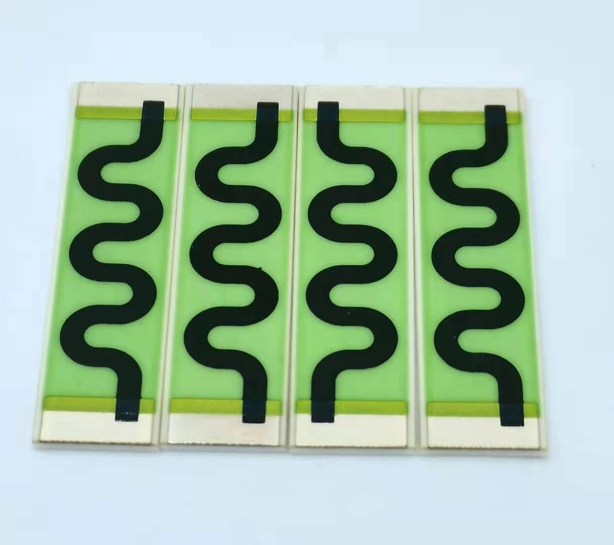
Provide the printed material route, resistor outline, terminal overlap, trim geometry, substrate, coating and installed heat path. A film resistor on ceramic, a polymer carbon resistor on FR4 and a packaged power resistor do not share a universal pulse limit. Even two ceramic patterns with equal resistance can distribute local current and heat differently around narrow regions or trim cuts.
The supplier and application owner must agree which representative specimens and acceptance observations address the declared pulse. Resistance change, visible damage, terminal integrity and insulation may require separate endpoints. One survived pulse does not establish repetitive endurance, and the absence of a visible mark does not prove that resistance or insulation remained within its requirement.
Release the pulse definition alongside the resistor request
The final application record contains the source circuit, initial stored energy, measured terminal waveform, calculation interval and energy balance. It names the repetition sequence and starting thermal condition, including any incomplete cooldown between events. Report the delivered load separately from any subsequent component qualification result.
Reopen this record when a power supply, switch, cable, capacitor, series resistor or printed pattern changes. A component with the same nominal resistance can receive a different pulse after a source revision. Keeping source impedance with the drawing makes that change visible before production testing or field operation discovers it.
Provide the pulse at the resistor terminals
Send the source model and waveform needed to review the printed element's actual electrical load.
- Source schematic, series impedance and switching timing
- Initial capacitor voltage and capacitance where applicable
- Terminal voltage/current traces and energy integration interval
- Repetition sequence, starting temperature and mount
- Printed pattern, resistance range and required qualification endpoints
The drawing-upload form loads as you reach this section.