
On this page
A lower pull-up resistance makes a released open-drain signal rise faster, but it also asks the active driver to sink more current. A larger value saves low-state power while slowing the edge and making leakage more important. For a thick-film resistor network, the useful specification is a valid resistance interval derived from the connected circuit, not simply a nominal value copied from another board.
System boundary
A printed pull-up resistor, its reference supply, one or more open-drain outputs, the receiving input and the connected node capacitance. Device compatibility and protocol compliance remain with the electronics designer.
Integration interfaces
| Interface | Required input | Thick film role | Validation owner |
|---|---|---|---|
| Pull-up supply to printed resistor | Supply extremes, resistance tolerance, temperature change and duty of the low state. | The resistor establishes charging current and dissipates power while the line is low. | Circuit designer supplies the functional resistance interval. |
| Open-drain driver to shared node | Guaranteed low voltage at sink current and release behavior of every attached device. | A small pull-up can demand more sink current than the weakest output supports. | Electronics owner checks device limits. |
| Released node to receiver decision | Node capacitance, high threshold, input leakage and sampling time. | Resistance and capacitance determine when the receiver can recognize a high state. | Digital interface validation owner verifies timing. |
Integration risks
| Risk | Control or verification | Validation owner |
|---|---|---|
| A newly connected board adds a parallel pull-up and overloads the low-state driver. | Calculate equivalent installed resistance at each population configuration. | System hardware owner. |
| Rise time is measured with different threshold percentages from the receiver requirement. | Record the exact start, end and sampling thresholds used. | Signal-integrity test owner. |
| A nominal value passes while its tolerance endpoint has no timing margin. | Apply all constraints to the full justified resistance and capacitance range. | Network and circuit drawing authorities. |
System integration decisions
- Identify the actual receiver thresholds and required valid-high time.
- Intersect low-state sink current, released-node charging and leakage constraints.
- Include every installed pull-up and the resistor's full applicable resistance range.
Define the released signal and its receiving threshold
Draw the pull-up supply, resistor, output transistor and all receivers connected to the node. In the simple topology considered here, the transistor actively pulls low and the resistor charges the node when the transistor releases. The receiver does not necessarily recognize a high state at the moment the output command changes; its actual threshold and the node waveform determine that event.
Identify whether the requirement is a rise time between two voltage percentages, a time from release to the high threshold, or a setup interval before sampling. Those quantities differ even for an ideal exponential. If a communication standard applies, use its current applicable requirements together with the selected device limits. The illustrative calculation below does not assign a protocol speed or certify a communication interface.
Derive the resistance lower bound from the low-state driver
The resistor current while the line is low is approximately the pull-up supply minus the low-state voltage, divided by resistance. Use the voltage at which the selected driver guarantees the needed sink current, not an assumed perfect zero-volt switch. Check the weakest device that may hold the shared line low, including temperature and supply conditions.
For an assumed 5-volt pull-up, a guaranteed 0.4-volt low level at 4 milliamperes would require at least 1150 ohms under that simplified limit. These are deliberately selected example inputs, not a specification for a company product or a particular logic family. A lower resistor would require more than the stated sink current at the selected voltage boundary.
Rmin = (Vpullup,max − VOL,max)/IOL
- Rmin is the resistance lower bound in ohms for the stated guaranteed low-state condition.
- Vpullup,max and VOL,max are volts; IOL is the applicable guaranteed sink current in amperes.
Single resistive pull-up to the named supply. Additional pull-ups, driver characteristics and leakage must be included in the complete circuit.
Derive the upper bound from the actual high-state decision
For an initially low node charging through a resistor into a lumped capacitance, the ideal voltage is the final supply multiplied by one minus exp(−t/RC). If the initial voltage is not zero, use the complete expression with the measured initial level. Time to a chosen threshold depends on the logarithm of its distance from the final voltage.
With an assumed 200-picofarad node and a high threshold at seventy percent of the final voltage, reaching that threshold within 1 microsecond requires R no greater than about 4153 ohms when starting at zero. The factor is minus ln(0.3), about 1.204. This is a release-to-threshold calculation; it must not be mistaken for a thirty-to-seventy-percent rise-time limit.
tH = −RC ln[(Vpullup − VIH)/(Vpullup − Vinitial)]
- tH is time from release to the required high threshold.
- C is lumped node capacitance and R is effective charging resistance.
- VIH is the receiver high threshold; Vinitial is the release voltage.
Constant supply, passive first-order charging, negligible leakage and no active rise-time accelerator. Distributed wiring requires a more complete model.
Apply tolerance to the intersection, not to either limit alone
The assumed examples produce a nominal feasible interval from 1150 to about 4153 ohms before other allowances. A chosen resistor must remain inside the applicable interval at its resistance endpoints. A 3.3-kilohm part with a hypothetical five-percent total resistance range spans 3135 to 3465 ohms, which fits that preliminary interval. This does not include a capacitance or leakage allowance yet.
If node capacitance doubles to 400 picofarads while the one-microsecond requirement remains, the timing upper bound falls to about 2076 ohms. The same 3.3-kilohm selection no longer fits, despite unchanged room-temperature resistance accuracy. Reducing resistor tolerance alone cannot repair a nominal value above the timing bound. Revisit capacitance, timing, driver strength or the interface architecture.
Check whether the released node can reach a valid high at all
Receiver leakage, contamination paths and connected protection circuits can draw current after release. With a bounded current IL to the low reference, the approximate final node voltage is Vpullup−IL R when a constant-current model is justified. A threshold close to that final value can be reached much later than the ideal no-leakage calculation predicts, or never reached.
Record leakage direction and its temperature dependence rather than assuming every input current pulls down. An unpowered attached device may create a nonlinear clamp instead of a small leakage term. That state needs a circuit and device-limit review. It is not valid to increase pull-up strength indefinitely to force a high level into a pin whose supply condition does not permit it.
Choose a remedy from the limiting inequality
Use the complete node model to identify the constraint that failed. A cleaner waveform is useful only when the low-state voltage, current and device conditions remain acceptable. Keep the following checks with the resistor drawing so a later board or cable change reopens the right decision.
| Failed condition | Meaning | Useful design response |
|---|---|---|
| Resistance below the low-state bound | Driver sink demand is too large | Increase equivalent resistance or select a suitable driver |
| Resistance above the timing bound | Released edge misses the decision time | Reduce capacitance or resistance within the sink limit |
| Final high voltage below the receiver threshold | Leakage or a clamp prevents a valid state | Identify the actual loading path |
| No overlap between the bounds | No passive resistor value satisfies both assumptions | Change the interface architecture or justified requirement |
| Only the populated system fails | Parallel pull-ups or additional capacitance were omitted | Recalculate the as-installed node |
Verify dissipation and measure without dominating the node
Low-state resistor dissipation is approximately the square of the voltage across it divided by resistance. Average dissipation depends on the low-state duty, but a long held-low fault can create a different thermal condition from ordinary toggling. Supply the relevant continuous and pulsed states for printed-resistor review; do not infer a power rating from the nominal resistance or occupied ceramic area.
Use a probe whose capacitance is included in the test. A probe that appreciably increases node capacitance can make the edge appear worse than the installed circuit, while a test fixture that omits the production harness can make it appear better. Measure at the actual receiver boundary and retain the low level, released waveform, supply and timing markers.
Release the complete pull-up function with the passive network
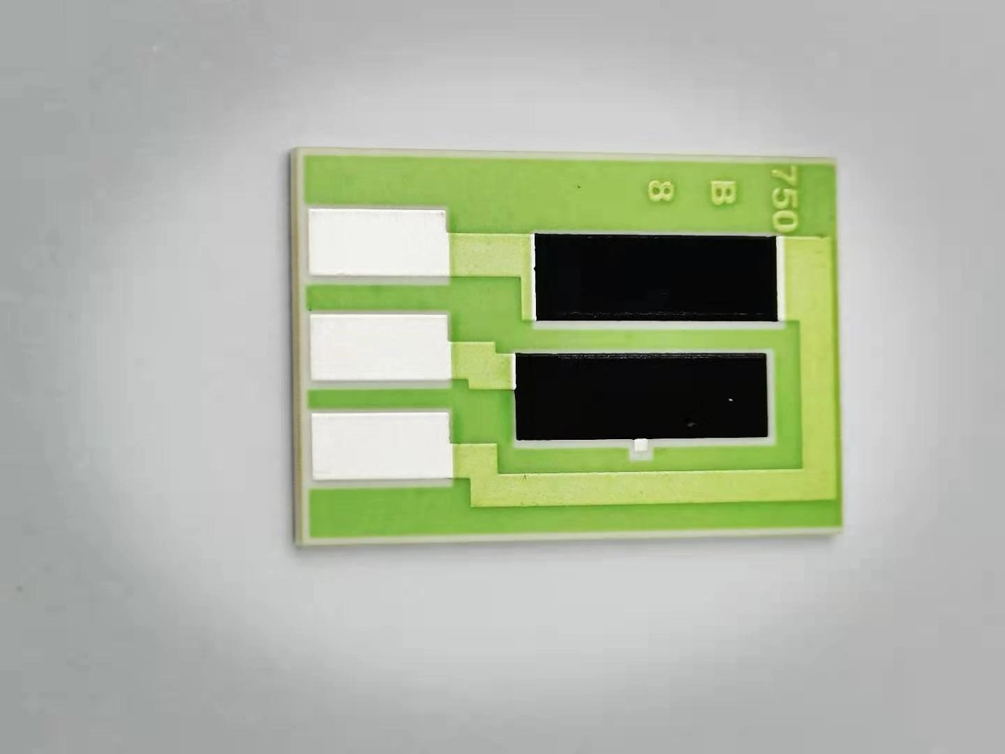
Identify the pull-up element and terminals separately from analog gain, sensing or diagnostic elements that share the ceramic. Provide its allowed resistance interval and operating conditions, plus the circuit analysis that produced them. If several resistors are fitted in parallel across connected modules, document the equivalent range for every permitted population state.
Retain the assembled low-state and released-edge verification with the network revision. Recheck after changing the receiver, driver, cable, protection network, pull-up supply or sampling schedule. The network supplier controls the drawing-defined passive element; the system team validates the complete node. That division makes the specification useful to purchasing without turning a resistor value into an unsupported communication-performance claim.
Review a printed pull-up resistor network
Supply the as-connected node and its valid-state requirements rather than a resistor value alone.
- Pull-up supply extremes and receiver high/low thresholds.
- Driver sink-current conditions and connected-device population.
- Node capacitance, leakage, required timing and measurement fixture.
- Resistance interval, low-state duty and intended resistor construction.
The drawing-upload form loads as you reach this section.