
On this page
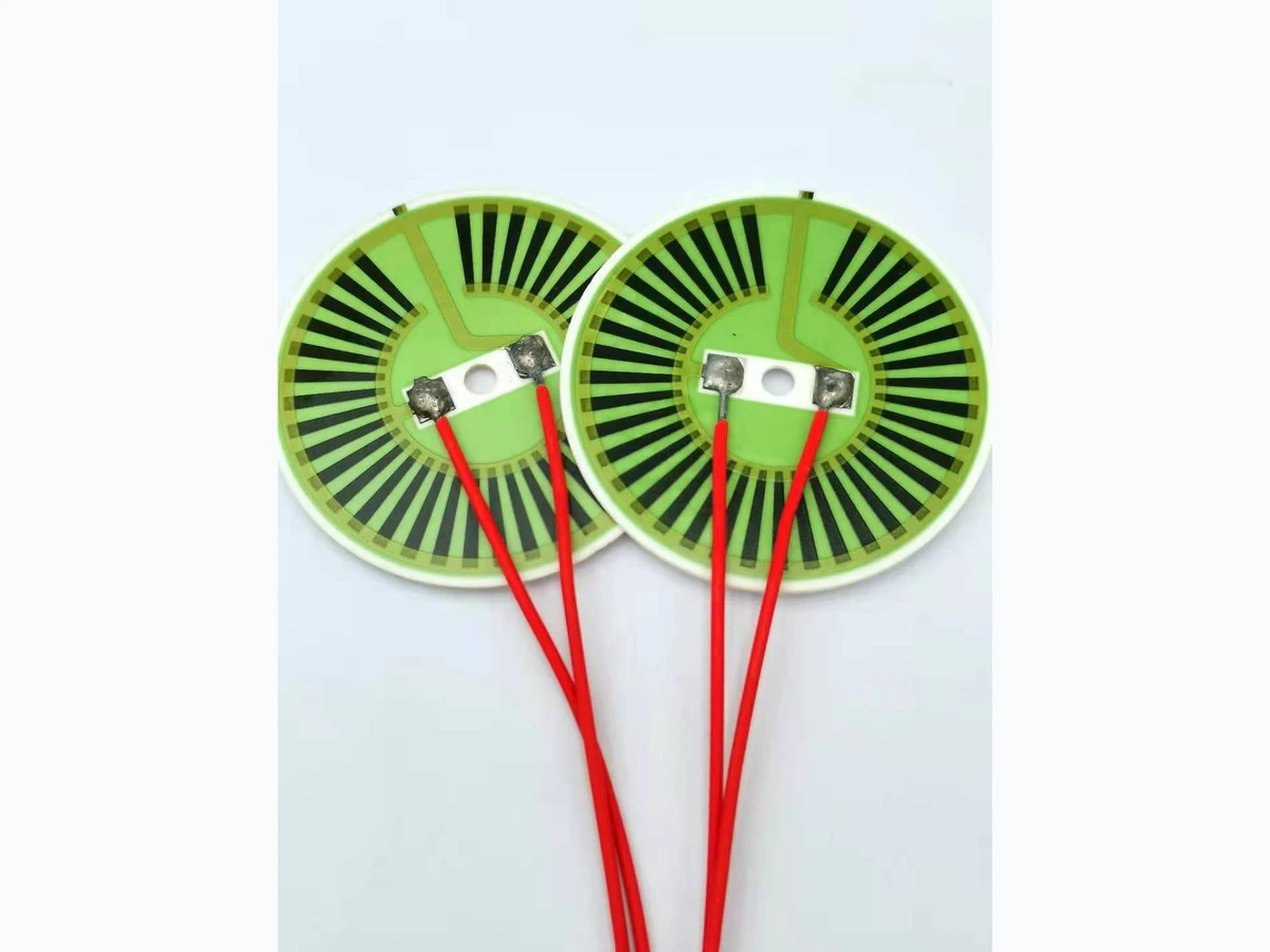
A ring heater can surround an optical opening without blocking it, yet its leads can still disturb alignment. A stiff cable, short service loop or displaced connector can apply force to the heater support and optical carrier. The first diagnostic step is to separate that mechanical input from temperature-driven movement, so the corrective action addresses the right interface.
System boundary
An annular thick-film heater, its lead terminations, cable route, connector and strain relief, heater support, optical carrier and alignment metrology. The optical-device owner retains authority for optical operation and any laser safety.
Integration interfaces
| Interface | Required input | Thick film role | Validation owner |
|---|---|---|---|
| Cable route to heater termination | Free length, bend orientation, cable stiffness, connector position and handling loads. | Heater leads must convey current without making the termination an unintended cable anchor. | Electrical and mechanical integrators review strain relief. |
| Heater support to optical carrier | Mounting contacts, shared brackets and reaction-force path. | The heater mount can transmit lead forces to alignment-sensitive structures. | Optomechanical engineer verifies displacement sensitivity. |
| Carrier motion to optical observation | Mechanical fiducials, optical coordinate, thermal baseline and stable external reference. | Heater-related mechanical effects must be separated from its thermal function. | Optical metrology owner defines and validates the comparison. |
Integration risks
| Risk | Control or verification | Validation owner |
|---|---|---|
| A strain relief attached to the optical carrier still transmits cable disturbance into alignment. | Draw the complete reaction path and compare an independently supported route. | Optomechanical owner. |
| Routing trials change temperature while movement is attributed to cable force. | Establish a non-heating stable-temperature baseline and retain temperature records. | Validation engineer. |
| A coupling-power change is mistaken for displacement. | Use independent source/detector checks and a defined mechanical or optical coordinate. | Optical metrology owner. |
System integration decisions
- Trace the cable reaction into the optical support, not only the heater terminal.
- Compare routing states at a stable non-heating baseline.
- Validate mechanical relief and thermal performance separately after changing the route.
Follow the cable load to its final support
Mark the cable connector, free span, bends, clips and terminal attachment on a drawing of the assembled optical module. A clip close to the heater can protect the soldered connection while still transferring the same external pull into a bracket shared with the optic. Terminal protection and alignment isolation are different objectives.
Identify where the reaction should enter the equipment structure. An independent chassis support may reduce the load reaching the carrier, but only if the remaining free cable segment can accommodate the specified motion. Avoid a routing arrangement that becomes taut when a cover closes or a service connector is installed.
Include the moment created by an offset lead exit
A force applied away from the carrier's reaction centre creates a moment as well as translation. For an illustrative perpendicular force of 0.2 N at a 20 mm lever arm, the moment is 0.004 N·m. Moving the same cable force to a 5 mm arm reduces that geometric moment to 0.001 N·m.
The example compares load paths, not allowable force or resulting optical displacement. Carrier stiffness, joint friction and contact location determine the response. A symmetric-looking pair of leads does not guarantee cancellation because their bend histories and restraints can differ. Measure the actual route's effect rather than assigning a universal cable torque from its diameter.
Establish a non-heating alignment baseline
Begin with heater power inhibited through the approved equipment state and with the assembly thermally settled. Record the carrier, support and surrounding temperatures sufficiently to detect drift during the routing comparison. Do not use an energized heater to stabilize temperature if that introduces the thermal variable the first experiment is intended to remove.
Define a mechanical coordinate on the carrier and a stable reference outside the cable-loaded path. If optical metrology is used, operate it only under the device owner's safe procedure. Optical signal amplitude alone may change with source or detector drift, so establish what observation actually represents position or angle.
Compare realistic cable positions without disturbing the mount
Choose a small set of permitted routing states, such as the service loop before enclosure closure, the final clipped route and the same route with an independent temporary support. Preserve the heater mount and optical adjustment throughout the comparison. Re-seating a clamp between trials would introduce another cause of movement.
Move only the designated cable segment using a controlled method that does not exceed the approved handling envelope. Record the route photograph or coordinates, mechanical displacement and thermal baseline. Return to the initial routing state to determine whether the position recovers or leaves a residual. A residual calls for investigation of slip or seating, not automatic subtraction as measurement drift.
Use an independent support as a diagnostic control
A temporary fixture that carries the remote cable weight can help test whether the carrier is reacting to the harness. Its purpose is to change the mechanical load path while leaving the electrical and optical configuration otherwise stable. It must not press on the heater, alter the carrier clamp or obstruct required access.
If the alignment response becomes smaller with that support, the comparison supports a cable-load contribution. It does not by itself specify the final strain-relief design. The production solution must also accommodate vibration, thermal motion, service access and electrical insulation requirements, using the real cable rather than an unusually compliant laboratory substitute.
Distinguish cable force from other movement mechanisms
Interpret the paired observations together. Timing correlation is useful, but the controlled change and independent references are what make the comparison informative.
| Observed response | Supporting check | Next action |
|---|---|---|
| Carrier moves immediately with routing at stable temperature | Independent support reduces the movement | Review mechanical cable reaction and relief location |
| Carrier moves while the external reference also moves | Metrology base or fixture disturbance | Stabilize the observation path before assigning the cause |
| Optical signal changes without measured carrier movement | Source, detector and relevant optical coordinate | Check whether the optical proxy represents alignment |
| Position does not recover after returning the cable | Mount or joint inspection in original coordinates | Investigate slip or seating before thermal trials |
| Movement develops only after heating begins | Spatial temperature and cable/support expansion | Continue with the separate thermal-alignment analysis |
Recheck heat paths after the mechanical correction
A relocated cable or clip can change heat conducted away from the ring heater. It can also change the temperature and stiffness of the lead segment during operation. After the non-heating mechanical issue is addressed, repeat the relevant powered thermal and alignment evaluation with the final route.
Keep the results separate: a successful static routing comparison does not establish hot alignment stability, and improved temperature uniformity does not prove that cable handling is harmless. The installed product needs both conclusions under their defined conditions. Preserve the same carrier and cable coordinates so the two records can be connected.
Make the accepted route reproducible after service
Specify clip locations, connector position, free cable length and any prohibited contact with the carrier or retaining hardware. Photographs should show the completed route from useful angles without replacing dimensional controls where small changes matter. Include the order in which the cable is connected and the optical mount is secured.
Verify that normal service restoration reproduces the accepted routing state without requiring undocumented hand adjustment for best optical signal. The final handoff should identify the reaction support, mechanical and optical observation coordinates, non-heating comparison and powered follow-up. This prevents a later harness change from being misdiagnosed as a defect in the ring heater's temperature control.
Review ring-heater lead forces and optical alignment
Provide the full cable and support arrangement so mechanical disturbance can be separated from the heater's thermal effect.
- Heater termination, optical carrier, clamp and chassis-support drawings.
- Cable construction, route, connector location, free span and service sequence.
- Stable-temperature routing observations with independent mechanical and optical references.
- Final powered temperature/alignment records and application-owned acceptance criteria.
The drawing-upload form loads as you reach this section.