
Overview
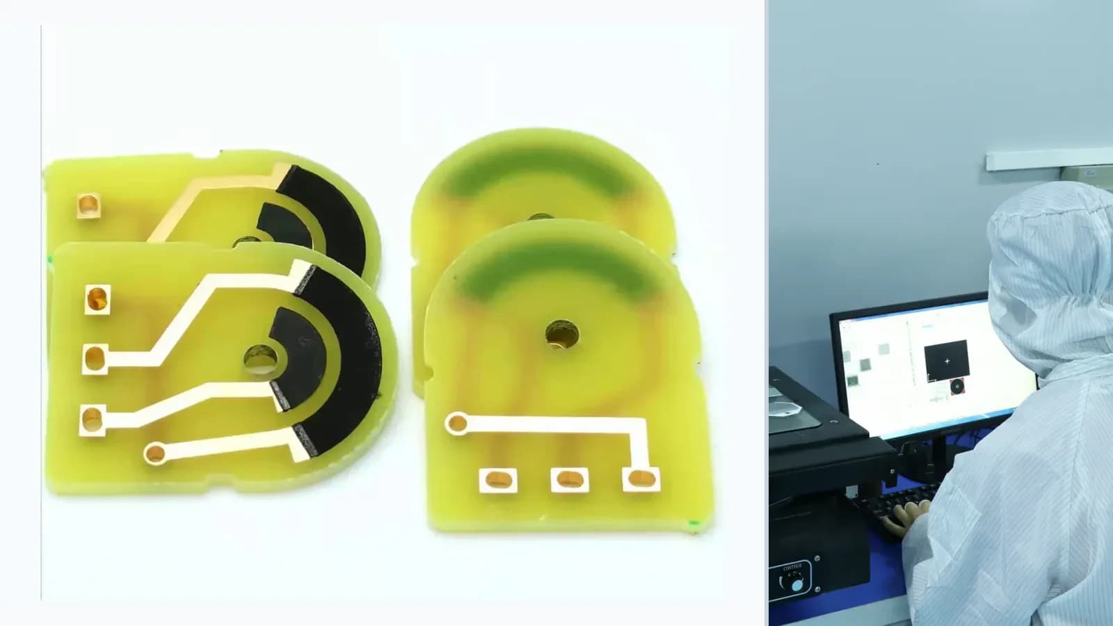
This engineering review example defines the evidence structure for FR4 Carbon-Film Potentiometer Engineering Review. No customer, result, performance improvement, yield, schedule, or volume is asserted because a traceable and publication-cleared project record has not been supplied.
Evidence release route
The order makes assumptions and ownership visible before a result is promoted to a requirement.
- 01
Confirm publication permission
For FR4 Carbon-Film Potentiometer Engineering Review, verify written publication permission, permitted evidence, redaction scope, and the named approver before external use.
- 02
Redact customer identity and drawings
For FR4 Carbon-Film Potentiometer Engineering Review, remove customer identity, confidential geometry, drawing data, lot codes, and other protected information while preserving technical traceability.
- 03
Verify input and process records
For FR4 Carbon-Film Potentiometer Engineering Review, agree the inspection method, sample plan, acceptance criteria, traceability, and report format before validation.
- 04
Verify measured outcome
For FR4 Carbon-Film Potentiometer Engineering Review, agree the inspection method, sample plan, acceptance criteria, traceability, and report format before validation.
- 05
Approve the bounded case narrative
For FR4 Carbon-Film Potentiometer Engineering Review, close remaining assumptions and link the quoted or released scope to the drawing revision, evidence set, owner, and change-control plan.
Engineering review matrix
Each row links a design variable to evidence that can support a drawing or release decision.
| Variable | Control question | Verification route |
|---|---|---|
| Transfer function | For FR4 Carbon-Film Potentiometer Engineering Review, define travel or angle against resistance, ratio, voltage, curve points, endpoint behavior, and permitted error. | Measure complete forward and reverse transfer curves at controlled reference conditions. |
| Mechanical chain | Float, linkage, shaft, carrier, datum, stop, preload, and tolerance stack convert physical input into wiper position. | Correlate position with electrical output and record hysteresis and repeatability. |
| Contact interface | Wiper material, load, track finish, geometry, speed, vibration, and debris affect noise and wear. | Run contact variation, wear, interruption, and life tests with the mating contact defined. |
| Media and protection | Fuel, oil, water, additives, cleaning agents, humidity, and temperature can change track, conductor, protection, and terminals. | Expose representative assemblies under defined media, bias, temperature, time, and criteria. |
| Electronics and diagnostics | Excitation, input impedance, filtering, redundancy, plausibility, and failure detection shape usable output. | Validate channels and diagnostic states with the actual controller interface or controlled equivalent. |
Failure controls
These are review prompts, not evidence that every risk applies or that every test is available.
- A
Curve error from linkage geometry or incorrect breakpoint placement
- B
Output noise, opens, or drift from contact wear and contamination
- C
Channel mismatch or diagnostic failure in redundant tracks
- D
Media ingress, corrosion, swelling, or protection-layer damage
Inputs for a practical review
Unknown values may be labelled unknown. The review should convert uncertainty into an explicit decision or validation task.
Send Drawings- 01
Travel/angle geometry and datum scheme
- 02
Target curve table including endpoints and tolerances
- 03
Mating wiper material, load, speed, and life profile
- 04
Excitation, electronics input, diagnostics, and filtering
- 05
Media, temperature, vibration, wear, and calibration tests