
On this page
Prepared by Chipsimple Engineering Team, Engineering and technical content review
Published online August 10, 2026 · Reviewed August 10, 2026
ENGINEERING ARTICLE 18 / VOLUME 3
Laser Trimming Printed Resistors Without Trading Accuracy for Stability
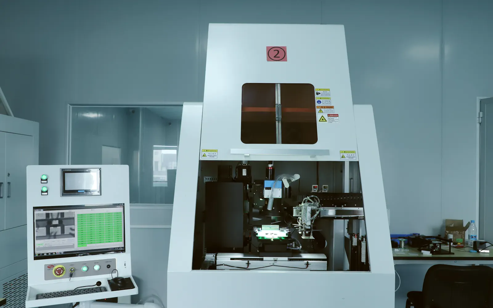
A trim cut removes or isolates resistor material, forcing current through a longer or narrower path and increasing resistance. The machine measures during the cut and stops at target. Resolution depends on resistor geometry, measurement noise, laser spot and cut strategy. Long-term stability depends on the remaining current path, thermal damage and post-trim conditioning.

Target the As-Fired Distribution
Trimming normally raises resistance and cannot rescue values already above target. Consequently, a broad or high distribution creates scrap while a very low distribution demands deep cuts. The engineering value comes from understanding the direction and sensitivity of the effect, not from memorising a nominal number.
A robust drawing or process plan will set paste, geometry and firing to a measured target below final value. This makes the design intent visible and gives the supplier room to use a qualified material set without changing the function.
The result can be checked through as-fired capability by resistor family and substrate position. Where possible, keep readings before and after the next thermal or mechanical operation; the delta often reveals more than the final value.
The failure pattern to investigate is long trim times and unstable geometries used to compensate for poor targeting. Before changing materials, confirm orientation, lot history, measurement method and acceptance limits.
Choose a Cut Shape for Resolution and Power
The physical starting point is straightforward: Plunge, L-cut and other paths change resistance sensitivity differently. From there, the trim tip and remaining neck concentrate current and heat. For laser trimming thick film resistor, the important issue is the amount of process margin left after normal variation is included.
On the drawing and in the review record, select cut path, entry, direction and maximum depth for each geometry. Keep the requirement functional wherever possible, while making any safety- or interface-critical boundary unambiguous.
A production trial should capture magnified cut dimensions and powered temperature or drift testing. Record the condition of the specimen and the next operation so that a later change can be traced to a specific stage.
If the team sees hot spots or cracks at an excessively deep trim tip, pause before adding inspection or rework. First check whether the layout and the qualified process window are asking for contradictory outcomes.
Control Measurement During Trimming
In a stable manufacturing route, contact resistance, probe stability and thermal state affect stop accuracy. This means an accurate laser cannot overcome noisy or warming measurement. The observation is especially useful because it connects a visible feature to an electrical, thermal or mechanical consequence.
The control plan should use stable probing, appropriate current and settling criteria. It should also name the drawing characteristic or coupon that represents the requirement, avoiding an instruction that depends on personal interpretation.
Evidence comes from repeat readings after probe release and controlled delay. A trend across position or lot is usually more valuable than a perfect reading from one hand-picked sample.
Investigate systematic overshoot or value bounce that follows fixture condition. The pattern may identify a narrow process interaction long before the final circuit becomes an open, short or out-of-tolerance value.
Limit Laser-Induced Damage
A useful way to frame the decision is this: Energy density, focus, speed and pulse conditions determine removal and heat-affected zone. As a result, excess energy can microcrack resistor, dielectric or ceramic. That cause-and-effect chain should remain visible when laser trimming thick film resistor is reviewed with purchasing and quality teams.
The manufacturing boundary is protected when the team can qualify laser settings and maintain focus and extraction. This approach separates the customer's functional need from the supplier's machine-specific compensation.
Confirm the decision with cut microscopy and stability tests after thermal conditioning. Include both typical and boundary-condition specimens where the failure consequence justifies them.
The symptom immediate pass followed by drift or intermittent behaviour deserves a structured investigation. Check material lot, artwork position, thermal history and measurement setup before assigning a single cause.
Stabilise and Verify the Final Value
Geometry and material meet at this point: The resistor may relax after trimming or later thermal exposure. Therefore, shipping a value measured only at the trim station can hide subsequent change. A nominal specification that omits the interface is incomplete even if every individual value looks reasonable.
During release, define post-trim dwell or stabilisation and final measurement conditions. Make sure the acceptance method measures the same physical feature that the design calculation assumed.
Useful confirmation includes final value, TCR or ratio after the agreed conditioning. Keep photographs or sections tied to part, revision, lot and orientation so they remain evidence rather than decoration.
One failure signature is lot drift between trimming and final customer test. It often becomes clear only when results are sorted by position, process stage or exposure instead of being combined into one average.
A Worked Engineering Review
A 1 kΩ resistor is designed to fire below target with enough area for an L-cut. Production data show the expected as-fired distribution and the trim program limits the cut before a minimum neck. Measurement current is chosen to avoid self-heating, and the fixture confirms stable probe contact before the laser starts. After trimming, parts rest or receive a defined stabilisation cycle and are measured again. A sample is inspected for cut geometry and tested under rated power. The process demonstrates stability instead of treating the trim station reading as final truth.
Design Review Checklist
- Set an evidence-based as-fired target.
- Define cut shape and maximum depth.
- Control probe and measurement current.
- Qualify laser energy and focus.
- Stabilise and remeasure after trimming.
Questions Engineers Commonly Ask
Can laser trimming lower resistance?
Standard material-removal trimming raises resistance. Special structures can provide alternative adjustment, but they must be designed explicitly.
What is a safe trim percentage?
There is no universal value. It depends on paste, geometry, power and cut strategy. Qualify a maximum cut geometry and stability window.
Why measure after a delay?
Thermal and material relaxation plus probe effects can cause the immediate value to differ from the stable final reading.
Related Engineering Resources
Closing Note
Laser trimming should make a capable resistor precise, not make an incapable process barely acceptable. Control the as-fired distribution, cut geometry, measurement and stabilisation as one system.