
On this page
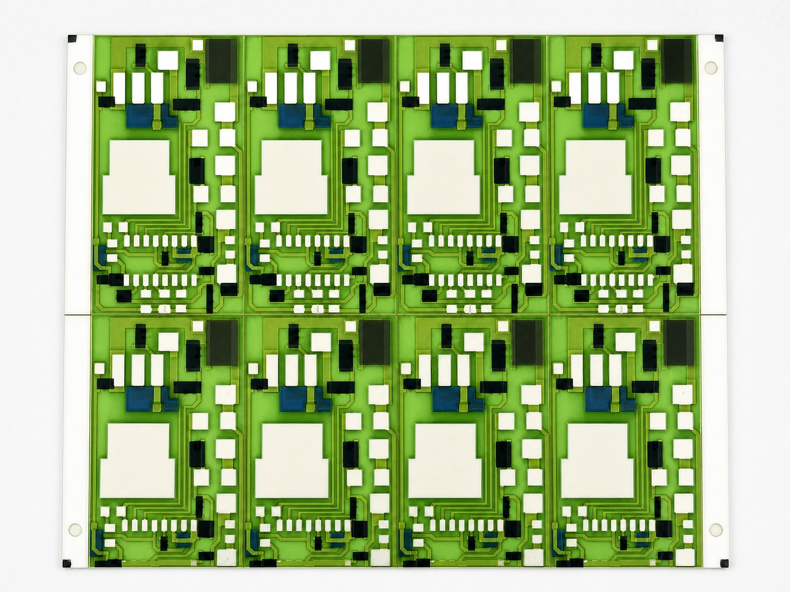
A panel-position result loses value if the individual ceramic circuit cannot be found after singulation. Tray row numbers, loading direction and removed rejects can all change the apparent order. The transfer needs an explicit mapping from parent panel position to physical destination, including empty locations and removed specimens. Counting the right number of parts is necessary, but it does not prove that their identities stayed attached.
Measurement purpose
Verify preservation of individual ceramic-circuit identity between parent panel positions and later tray or sorting locations.
Specimens and conditions
- Source array
- Identified panel, declared face, row/column convention and asymmetric witness
- Destination
- Identified tray with orientation, occupied pockets and removal states
Equipment and records required
- Physical identification: Approved labels, mapped carriers or suitable witnesses that do not damage product
- Mapping verification: A record system supporting unique source/destination associations and reverse lookup
Method sequence
- Source definition
Record positions before singulation removes orientation features
Record: Parent map
- Transfer
Capture each destination and all sample/reject removals
Record: Source-to-destination event
- Challenge
Verify counts, uniqueness, orientation and reverse trace
Record: Transfer validation
Decision and uncertainty
Accept identity transfer only when every physical item and occupied destination has a consistent, reproducible association.
Balanced counts do not prove identity; lost physical linkage cannot be repaired by guessing from electrical values.
The traceability owner defines identifiers; operations and quality verify physical execution.
Traceable outputs
| Record | Required contents |
|---|---|
| Transfer map | Panel origin, current container/pocket, orientation, status and event identity |
| Exception ledger | Removed samples, rejects, partial trays, rotations and unresolved identity scope |
Method review decisions
- Define panel and tray orientation independently.
- Map every transfer, including rejected and sampled positions.
- Verify both one-to-one identity and quantity reconciliation.
Name the panel positions before separating the parts
Assign a stable panel identifier and position convention while the panel is still intact. State which face is viewed, where row one begins and which direction columns increase. Include an asymmetric physical witness that survives or remains documented when rails are removed. A diagram without orientation can be interpreted correctly in two opposite ways by different workstations.
Separate the permanent part identity from its current location. Panel P12 at row two, column three identifies an origin; tray T8 pocket five identifies a temporary destination. Replacing the origin with the destination breaks later analysis of print or firing position. Keep both fields and connect them through a transfer event.
Do not assume all loading orders are the same
A tray may be loaded row by row, column by column or in a serpentine path that reverses direction on alternate rows. The same sequential counter produces different destinations under those rules. Write the rule explicitly and verify it using a small known arrangement before using it for production identity.
An illustrative two-row, three-column panel contains positions A1, A2, A3 and B1, B2, B3. Row-major loading gives that order; serpentine loading gives A1, A2, A3, B3, B2, B1. Both contain six parts and the same identifiers, so a quantity check passes even when a downstream program interprets the wrong order.
Treat tray rotation as a transformation, not a relabeling
If a tray is rotated, the physical pockets move while their defined identities remain. A top-left pocket in the operator’s current view is not necessarily pocket one. Use a keyed orientation or a visible orientation mark and verify it before reading the map. Mirrored views of the opposite face require a different transformation from a simple in-plane rotation.
For a rectangular map with R rows and C columns, a half-turn maps row r, column c to row R plus one minus r, column C plus one minus c when coordinates are re-expressed in the fixed viewing convention. Verify the actual movement with corner and interior witnesses. This arithmetic describes indexing only; it does not authorize rotating a product when handling or contamination controls prohibit it.
r′ = R + 1 − r; c′ = C + 1 − c
- R and C are the map row and column counts.
- r and c are one-based source indices.
- r′ and c′ are indices after a half-turn in the declared fixed view.
A complete rectangular array and a 180-degree in-plane rotation are assumed. Missing positions retain their identities rather than collapsing the array.
Keep holes in the sequence when parts are removed
If a circuit is removed for a destructive test or rejected during inspection, record that position and destination. Do not automatically shift every later identity forward to close the gap. Compacted packing is possible, but it needs an explicit source-to-destination list that differs from the original panel array.
Mixed trays require item-level associations. A tray containing parts from two panels is not one homogeneous panel population simply because it has one label. Preserve the panel origin, current pocket and status of every item. Where the process requires homogeneous groups, verify that condition before loading rather than discovering the mixture during an investigation.
Verify the transfer as a one-to-one relationship
Every transferred item should have one destination, and every occupied destination should resolve to one item. Duplicate destinations, missing origins and unidentified extras indicate different faults. A mapping can have balanced quantities while exchanging two identities, so include physical witnesses as well as database checks.
| Check | Error it detects | What it does not prove |
|---|---|---|
| Source count equals transferred plus removed count | Unaccounted material quantity | Correct identity of each transferred part |
| No duplicate destination pockets | Two records assigned to one location | The recorded item was physically placed there |
| Every occupied pocket has one source identity | Unidentified extras or incomplete records | Orientation convention is correct |
| Asymmetric corner and interior witnesses agree | Common rotation, reflection or ordering mistakes | Every unobserved transfer was correct |
| Reverse lookup returns the original panel position | Broken ancestry in the data model | The underlying physical identity was captured correctly |
Preserve identity through electrical binning and rework
Sorting by resistance or inspection status creates a new ordering that no longer follows panel position. Record the movement as a new event rather than rewriting the original tray map. When a circuit is retested or reworked, its permanent identity should remain stable while its state and location change.
Do not infer identity from the measured value. Two circuits can have similar resistance, and a later process can change it. Matching a spreadsheet row to the nearest resistance in a tray is not a reliable reconstruction method. If identity is lost, record the affected population and assess containment; a plausible numerical match should not become invented genealogy.
Test the mapping workflow with deliberate exceptions
Before relying on the workflow, use a controlled nonproduction challenge containing a missing position, a removed sample, a rotated tray and a partial refill. Confirm that the operator instructions and data system preserve the intended identities in each case. Use harmless, clearly identified witnesses rather than marking saleable ceramic surfaces without approval.
Perform both directions of the trace. Start from a finished pocket and recover the parent position, then start from a parent position and find its current destination or removal record. These queries expose different errors. Include a repeat after a software, tray-size or loading-order change, because a map validated for one arrangement may be misread by another.
Carry the physical map into the inspection record
The final record links panel identity, source position, destination container and pocket, transfer time, status and any removal reason. Attach the orientation definitions and the verified loading rule. The result allows a resistance pattern or damaged region to be traced back to its actual panel location instead of being attributed to whichever tray row happened to receive it.
This transfer map complements the layer and firing traveler. It does not replace material history, and a complete genealogy does not itself establish product conformance. ChipSimple can review required identification and reporting by project; any customer-specific traceability claim must match the actual implemented and verified process.
Specify required panel-to-part traceability
Provide the mapping and reporting expectations before panel handling is defined.
- Panel array, face convention and orientation features
- Tray geometry and permitted loading order
- Sample removal, sorting and rework requirements
- Required permanent IDs and customer report keys
- Transfer challenge and reverse-trace acceptance expectations
The drawing-upload form loads as you reach this section.