
On this page
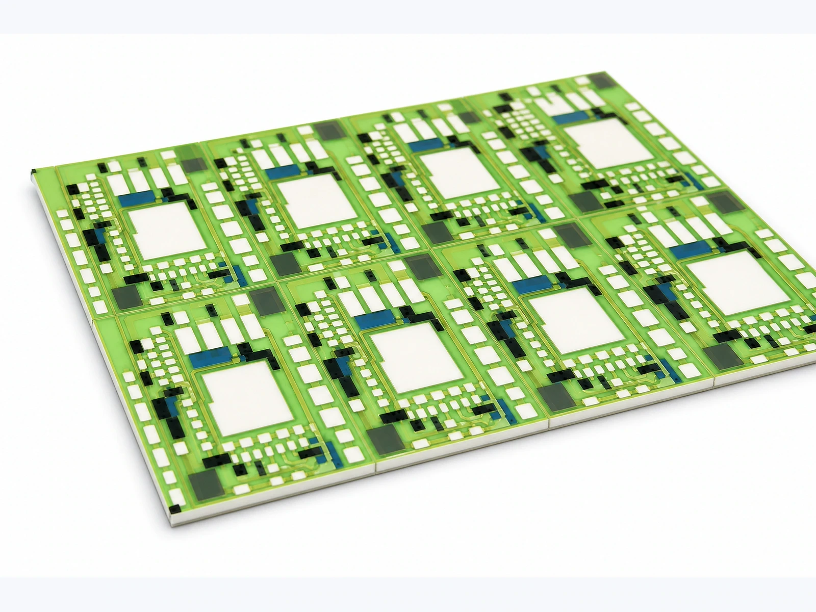
Cutting a coated ceramic panel into smaller witnesses preserves much of its face area while creating additional exposed edges. Those edges can reveal substrate, conductor or polymer interfaces that the intact product does not expose in the same proportion. A compatibility comparison must therefore define face and edge exposure separately before attributing a larger change to the coating material itself.
Measurement purpose
Verify that chemical-exposure coupon comparisons account for the amount and construction of exposed edges as well as broad faces.
Specimens and conditions
- Coupon geometry
- Finished dimensions, holes, exposed faces and actual cut-edge layer structure
- Preparation state
- Documented cutting, cleaning, damage inspection and any edge seal
Equipment and records required
- Geometry characterization: Suitable dimensional and optical methods for the relevant edge and coating boundaries
- Exposure comparison: Controlled bath and functional measurements with location-specific observations
Method sequence
- Mapping
Identify wetted faces, edges and layer terminations
Record: Exposure geometry register
- Comparison
Calculate area ratios and select controlled edge-access variants
Record: Coupon comparison plan
- Interpretation
Separate edge, face and seal contributions using suitable observations
Record: Bounded interface conclusion
Decision and uncertainty
Compare specimens only with their exposed interfaces and normalization basis defined; equal broad-face area does not establish equivalent chemical access.
Kerf damage, roughness, seals, shielding and geometry-dependent exposure can confound ideal area arithmetic.
The material and application owners approve representative coupon boundaries and the functional acceptance criteria.
Traceable outputs
| Record | Required contents |
|---|---|
| Geometry evidence | Dimensions, face/edge areas, exposure map and preparation condition |
| Comparison result | Raw property changes, location observations, selected denominator and transfer limitations |
Method review decisions
- Record the actual exposed edge construction, not only coupon area.
- Compare perimeter-to-face relationships when coupon sizes differ.
- Treat an edge seal as an additional material and boundary condition.
Identify what is exposed at the cut
A cut can expose bare ceramic, a printed layer end, an adhesive bondline or the underside of a protective coating. Inspect the actual edge after preparation and record which interfaces reach the liquid. A drawing of the original panel does not show whether cutting chipped the glass, smeared material or opened a local separation.
Keep fired inorganic glass distinct from an organic overcoat or adhesive. Their exposure mechanisms and preparation sensitivity can differ. The geometry review identifies access paths; it does not assume that a green surface is chemically impermeable or that all cut-edge damage has the same effect.
Calculate face and edge area on the same geometric basis
For a rectangular coupon of length L, width W and thickness t, the two broad faces have area 2LW and the four perimeter edges have area 2t times (L plus W). This simple geometry excludes holes, bevels, roughness and coating relief. Use it as a comparison denominator only when those exclusions are acceptable for the question.
State whether one face or both faces are actually exposed. If one face is bonded to a holder, its nominal geometric area should not be counted as freely wetted. Likewise, a sealed edge is not part of the unsealed-edge area. The exposure map should distinguish geometric area from the area accessible to the test liquid.
Afaces = 2LW; Aedges = 2t(L + W)
- L, W and t are finished coupon dimensions in the same length unit.
- Afaces includes both broad faces; Aedges includes the four ideal rectangular perimeter faces.
Rectangular solid without holes or bevels. The actual wetted subset and any edge-preparation damage must be recorded separately.
See what singulation changes without changing material quantity
An illustrative 40 by 20 by 1 millimetre plate has 1,600 square millimetres of combined broad-face area and 120 square millimetres of perimeter-edge area. Dividing it into eight separate 10 by 10 by 1 millimetre squares preserves the same total ideal broad-face area but raises total edge area to 320 square millimetres.
The edge-to-face ratio rises from 0.075 to 0.20, even before considering kerf loss or cutting damage. A test that normalizes both sets only by broad-face area can therefore compare different amounts of interface access. These dimensions are hypothetical geometry, not a company product design or a chemical-resistance result.
| Configuration | Total broad-face area | Total perimeter-edge area | Edge/face ratio |
|---|---|---|---|
| One 40 × 20 × 1 mm plate | 1,600 mm² | 120 mm² | 0.075 |
| Eight 10 × 10 × 1 mm squares | 1,600 mm² | 320 mm² | 0.200 |
| Difference before kerf allowance | No change | 200 mm² additional edge | About 2.67 times the original ratio |
Use a comparison that isolates the edge question
To investigate edge sensitivity, choose a controlled set that changes the relevant edge access while retaining the material state and intended face exposure as closely as practical. Size variants can be informative, but their different thermal response, handling and specimen-to-bath ratio must be considered. Do not attribute every size effect uniquely to edge ingress.
Where an edge-sealed comparison is justified, include suitable seal-only or material controls. The seal may absorb liquid, release material, restrain swelling or change drying. It is not an invisible subtraction from the experiment. A sealed coupon that behaves differently identifies a boundary-associated effect only after these additional influences are evaluated.
Separate preparation damage from ordinary product edges
Record cutting method, orientation, cleaning and the interval before exposure. Examine representative edges before testing using a method that can resolve the relevant chips, cracks or layer terminations. A freshly cut research coupon may expose a route that a finished product edge does not contain.
If the product is itself singulated after coating, use the actual production-representative edge state where appropriate. If its edge is protected later, include that final protection in the representative assembly. Do not improve the coupon edge beyond the supplied product condition and then claim the result covers ordinary manufacture.
Map where the first change appears
Retain observations at the face centre, perimeter and any exposed layer termination. A change beginning at cut edges suggests a different investigation from uniform face change, but appearance alone does not prove the transport or reaction mechanism. Use suitable physical or functional evidence to test the proposed explanation.
For electrical measurements, identify whether the exposed edge can create a leakage path or affect a terminal interface outside the intended coating test. A whole-coupon resistance change may combine multiple mechanisms. Use the geometry map to select additional measurements rather than assigning all change to the broad-face coating.
Report the denominator and specimen state with every comparison
A mass change per unit broad-face area, per total wetted area and per initial polymer mass are different results. None is universally correct. Choose the denominator for the intended material question and retain the raw mass or property change so other interpretations remain possible.
Document whether the chemical test follows a specific agreed method or is a project development comparison. A full-surface plastic immersion method does not automatically describe a selectively coated ceramic assembly with sealed edges. Standards can inform the test design within their scope, but any adapted specimen boundary needs explicit technical review.
Transfer only the exposure boundary that was demonstrated
The final record should identify coupon dimensions, exposed faces, edge construction, preparation, sealing, bath arrangement and location-specific outcomes. Keep cut witnesses distinct from finished assemblies. An intact-face result cannot establish the behaviour of every opened edge, and a damaged cut coupon should not automatically condemn a protected product interface.
ChipSimple can review representative specimen geometry for a drawing-specific ceramic stack and application. The value of the edge-area review is a comparison that answers the actual access-path question. Combine it with the required functional measurements and actual fluid conditions before making a bounded compatibility conclusion.
Define representative chemical-exposure coupons
Show how the witness exposes the same interfaces as the finished product.
- Product stack and final edge construction
- Proposed coupon dimensions and cut method
- Exposed faces, openings and any edge sealing
- Fluid, bath volume and specimen-loading arrangement
- Functional measurements and required product transfer scope
The drawing-upload form loads as you reach this section.