
On this page
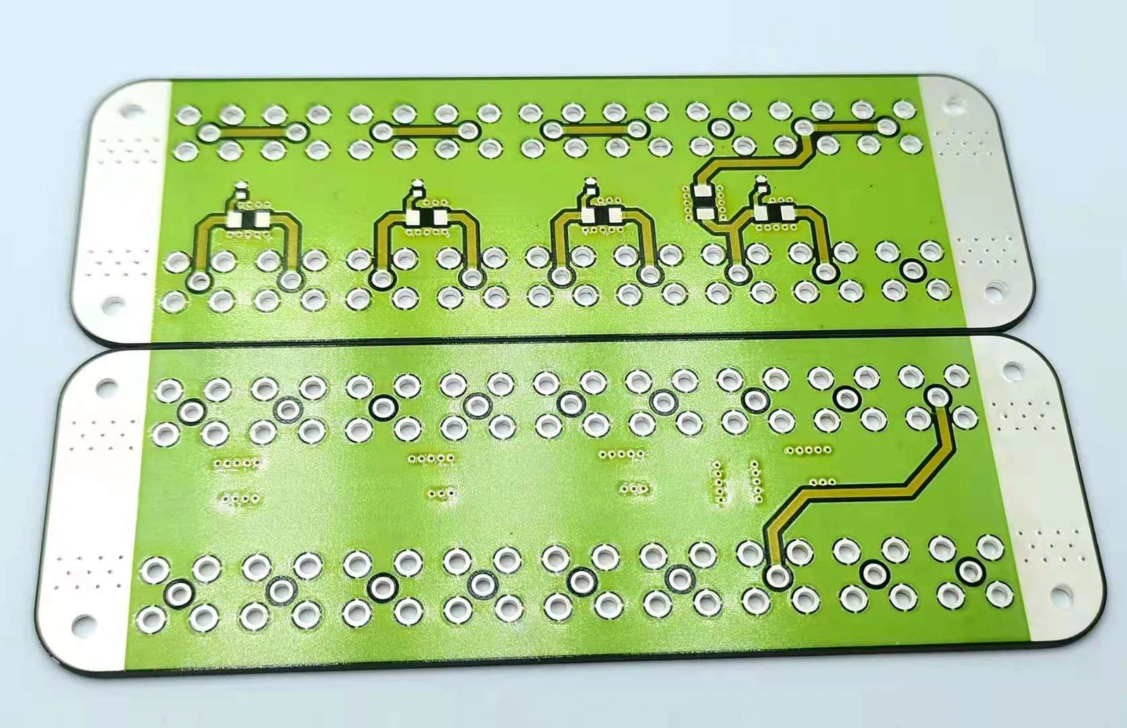
A new revision label does not prove that the ceramic pcb underneath contains the revised geometry or material. A replacement drawing can reach the reporting system before it reaches the screen, fixture or work in progress. Revision inspection therefore needs physical discriminators: features or controlled process records that distinguish the configurations actually at risk of being mixed. The check should answer which revision was built, not only which revision was printed on the traveler.
Measurement purpose
Verify physical revision identity across an engineering change.
Specimens and conditions
- Candidate set
- Relevant old, new and approved variant configurations identified.
- Change state
- Work-in-progress and effective operation boundary retained.
Equipment and records required
- Physical discrimination: Suitable imaging or metrology for distinguishing features and uncertainty.
- Genealogy verification: Controlled material and operation records linked to the specimen.
Method sequence
- Define differences
Build the revision-by-feature matrix.
Record: Controlled discriminator set.
- Inspect
Measure or observe features before they become hidden.
Record: Actual feature states and bounds.
- Reconcile
Resolve identity against process history and transition rules.
Record: Supported revision or contained ambiguity.
Decision and uncertainty
Assign a revision only when identity-critical differences are resolved.
Overlapping measurements and invisible material changes can prevent visual identification.
Engineering change and quality owners.
Traceable outputs
| Record | Required contents |
|---|---|
| Revision matrix | Candidate configurations, discriminators and required states. |
| Physical verification | Observed features, genealogy, effective boundary and identity decision. |
Method review decisions
- Select features that distinguish the new revision from every relevant old configuration.
- Keep physically observable changes separate from material or process changes that need genealogy.
- Evaluate measurement separation before using a small dimensional difference as a revision identifier.
Start with the actual revision difference
Compare the controlled old and new drawings and list each changed feature, material, operation and acceptance requirement. Separate editorial corrections from physical changes. A changed title or corrected note may not create an observable difference on the part, while a shifted pad or altered overglaze opening does. The inspection plan should state which changes can identify the configuration and which only affect documentation.
Include manufacturing data derived from the drawing: screen artwork, component placement, trim program, fixture map and test limits. A drawing revision can be correct while one derived file remains old. Do not assume that matching revision text across documents proves that their underlying content was regenerated. Retain the difference itself, not only the new revision letter.
Identify the configurations that can actually be present
List the old revisions, approved variants, partially processed material and reworked items that may share the same physical area. The new part must be distinguished from that set, not from an imagined generic predecessor. A feature that separates revision C from B may be identical in revision A, which could still exist in retained stock.
Keep the effective change boundary tied to material and operation state. A panel printed before a change and assembled afterward can have a mixed history. That does not automatically make it unacceptable, but it needs the approved transition rule. Do not assign the final revision solely from the date on which the last operation or inspection was completed.
Choose independent physical discriminators
Select features whose observed state differs between the relevant configurations: an additional pad opening, a moved terminal hole, a changed resistor connection or a defined component option. Prefer an unambiguous accessible feature when one exists. A label can support the check but should not be the only discriminator when the risk is a mislabeled physical build.
Use more than one discriminator when a single feature can be shared by another variant or altered through rework. Record the feature's location and accepted state for every candidate revision. Do not add a cosmetic mark to a saleable part without authorization just to simplify the inspection. The discriminator must either belong to the controlled design or be an approved identification feature.
Check whether a dimensional change is resolvable
Consider hypothetical slot-width ranges of 1.18–1.22 mm for revision A and 1.58–1.62 mm for revision B. With a conservative measurement bound of ±0.02 mm, the possible displayed intervals expand to 1.16–1.24 mm and 1.56–1.64 mm. Those intervals remain separated, so this feature can potentially distinguish the revisions under the stated method.
Now consider two allowed ranges that overlap after including uncertainty. A reading in the overlap cannot establish which revision produced it, even if it is closer to one nominal value. Add another physical discriminator or use traceable process evidence. These illustrative intervals demonstrate revision identification, not a manufactured tolerance or a substitute for the separate dimensional acceptance rule.
| Candidate | Allowed slot width | Measurement bound | Possible displayed interval |
|---|---|---|---|
| Revision A | 1.18–1.22 mm | ±0.02 mm | 1.16–1.24 mm |
| Revision B | 1.58–1.62 mm | ±0.02 mm | 1.56–1.64 mm |
| Interpretation | Intervals remain separate | Method must be valid | Useful identity witness, not complete conformance |
Build a revision-by-feature decision matrix
Create a matrix with candidate revisions as rows and discriminating features as columns. Fill it from controlled drawings before examining the mixed population. A specimen's observed feature combination should correspond to one permitted configuration. A combination that matches no row may indicate mixed manufacturing data, an unauthorized repair or a measurement problem.
Do not force an unmatched combination into the nearest revision. Preserve the actual feature states and investigate the transition history. The matrix also exposes redundant checks: two features that always change together may not add independent discrimination, while one apparently minor feature can separate otherwise identical variants. Select the necessary set without turning the inspection into a repetition of every first-article dimension.
Verify the first affected build and mixed work in progress
At introduction, inspect representative physical items at the operation where the distinguishing change first exists and again where later processing can hide it. Link those observations to the actual screen, program or material identity. A final package label cannot reconstruct a buried layer after closure, so capture relevant evidence while access remains available.
Check retained stock and work in progress against the approved effective boundary. Preserve old and new configurations separately where the transition requires it. If a later rework legitimately changes a discriminator, record the operation and the resulting approved configuration rather than merely relabeling the item. Recheck derived inspection and test files so the new build is not evaluated with an old mapping.
Release a revision identity with supporting evidence
The revision verification record should include the candidate set, distinguishing features, observed values or states, method uncertainty and linked process genealogy. State which configuration is supported and whether every identity-critical change has been resolved. Product conformance still requires its own dimensional, electrical and application checks; identifying revision B does not prove that every revision B requirement is met.
For an engineering change to a custom ceramic circuit, send the old and new controlled data together with the intended effective boundary and any mixed stock. ChipSimple can review drawing-specific changes and the inspection access needed to verify them. The practical goal is a revision claim that can be traced to the physical construction, not a collection of documents displaying the same new letter.
Send both sides of the engineering change
Provide the old and new data so physical differences and transition risks can be identified together.
- Controlled old/new drawings and derived manufacturing files.
- Changed geometry, materials, programs and acceptance requirements.
- Effective lot or operation boundary and remaining work in progress.
- Accessible discriminators, measurement limits and genealogy requirements.
The drawing-upload form loads as you reach this section.