
On this page
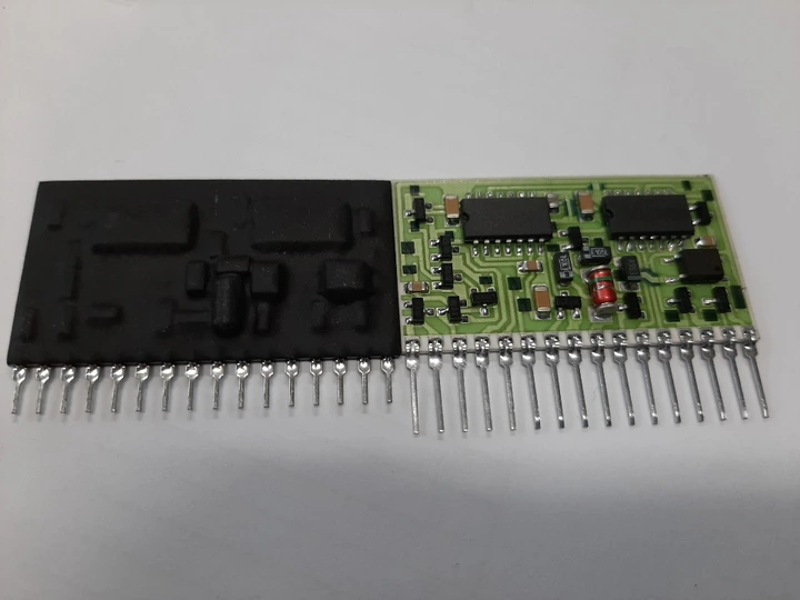
A top-down photograph can show a uniformly coated ceramic circuit while missing an unprotected terminal edge beneath a lead overhang. The inspection plan must identify which surfaces require polymer protection and which must remain clear for mating or testing. View access, coating presence and cure state are separate questions. Resolving them together prevents a bright, attractive top surface from concealing an unexamined functional boundary.
Measurement purpose
Verify required polymer coverage at terminal edges including occluded regions.
Specimens and conditions
- Stack identity
- Known polymer grade, terminal sequence and completed cure state.
- Zone map
- Must-coat, keep-out and inaccessible surfaces separately identified.
Equipment and records required
- Visual access: Defined oblique or side views that resolve the actual required surface.
- Material-specific inspection: Suitable fluorescence or thickness method only where validated for the named coating.
Method sequence
- Map
Allocate coverage and keep-out zones in section.
Record: Terminal surface map.
- Inspect
Record visible coverage and any hidden region.
Record: View-indexed observations.
- Close
Review cure and authorized corrections without losing original observations.
Record: Separate coverage, cure and keep-out dispositions.
Decision and uncertainty
Unobserved regions need justified evidence rather than an assumed visual pass.
Occlusion and fluorescence response limit what images prove.
Coating-process and assembly design owners.
Traceable outputs
| Record | Required contents |
|---|---|
| Coverage map | Required surfaces, view direction and observed or unresolved status. |
| Process closure | Cure history, touch-up scope, contact keep-outs and final disposition. |
Method review decisions
- Map must-coat and keep-out surfaces around each terminal in three dimensions.
- Treat an occluded region as unobserved, not automatically coated.
- Use fluorescence only when the named coating supports it, and do not equate brightness with cure or thickness.
Identify the polymer above the ceramic stack
List the coating grade, application route and cure state, together with the ceramic, fired conductors, resistor film, glass overglaze, solder and terminal materials it covers. A green fired glass layer is not a green polymer coating. The two have different formation and inspection requirements, so color cannot select the inspection method or a repair chemistry.
Record whether the terminal was attached before or after coating. A coating process qualified on a flat printed coupon may not reach the underside of an attached lead. Likewise, a terminal fitted afterward can damage a previously continuous film. The inspected state must represent the completed sequence required by the drawing rather than the easiest intermediate stage to photograph.
Draw the required coverage and keep-out zones
Use a section through the terminal to mark its top, side edges, underside, solder fillet and adjacent ceramic. Assign each accessible or hidden region a required status. Connector mating faces, test contacts and other functional interfaces may need to remain uncoated even when nearby insulation requires continuous protection. Resolve that boundary before asking an inspector to judge appearance.
Do not assume that more coating is always safer. Material entering a mating contact can interfere with connection, while a thick bridge across a gap can create a different mechanical condition from a conforming film. Translate the drawing into a zone map with dimensions and physical landmarks. A broad instruction to cover everything is not adequate for an assembly with exposed interfaces.
Plan views from the hidden surface outward
For each required region, identify at least one observation direction that can see the actual surface rather than only the overhanging terminal. Use a controlled side or oblique view where access permits. Show the camera or microscope direction on the inspection map. A bright fillet at the front edge may obscure an uncoated strip farther underneath.
Keep application access distinct from inspection access. A nozzle may reach a location that the camera cannot see, or the camera may see a region that was shadowed during deposition. Where a surface remains inaccessible, obtain a method capable of addressing it through an appropriate representative process study or authorized specimen examination. Do not label an invisible region as visually accepted.
Account for unobserved area explicitly
Consider an illustrative rectangular underside zone 6 mm long and 1 mm deep, giving 6 mm² of required coverage. Suppose the first side view resolves only the front 0.4 mm strip along its full length. The observed area is 2.4 mm², leaving 3.6 mm² unobserved. Complete visible coverage in that image therefore describes only 40 percent of the zone, not 100 percent of the terminal underside.
If an opposite view resolves another 0.4 mm strip with no overlap, 1.2 mm² in the center is still unobserved. Real terminal geometry and perspective can make the boundary more complicated, so map actual visible regions rather than adding image areas blindly. This area exercise measures inspection access; it does not estimate the probability of a defect or predict coating performance.
| Region | Area | Inspection status |
|---|---|---|
| Entire required underside | 6.0 mm² | Defined by drawing |
| Front strip visible from first view | 2.4 mm² | Can be evaluated in that view |
| Rear strip visible from opposite view | 2.4 mm² | Separate view, assuming no overlap |
| Central hidden strip | 1.2 mm² | Requires another justified method |
Interpret fluorescence within its actual limits
When the specified coating contains a suitable fluorescent tracer, controlled ultraviolet inspection can help locate coated and uncoated regions. Retain the excitation and imaging conditions, and follow the applicable optical safety procedure. A nonfluorescent material cannot be judged by the absence of a glow, and unrelated adhesives or residues can require identification before their fluorescence is attributed to the coating.
Brightness depends on the material, optical geometry, exposure and the layer being observed. Do not convert a bright image into a thickness value without a validated relationship for that coating and geometry. Fluorescence also does not establish that the film has reached its required cure. Keep presence, thickness and cure results in separate fields so one attractive image cannot stand in for all three.
Inspect after the required cure state
Record the specified cure sequence and the actual completed process record. Inspect the relevant terminal boundaries after cure because the wet shape need not represent the final film. Note pullback, discontinuities, trapped contamination and areas that no longer follow the intended surface. Apply the drawing's material-specific criteria instead of importing a universal cosmetic limit from another assembly class.
For a coating whose cure depends on direct light, determine how the named material's approved process addresses shadowed regions. A cured top surface does not establish the state beneath a lead. Do not improvise additional heat or chemical treatment. If the available cure evidence does not cover the hidden region, refer the unresolved material state to the process owner before functional acceptance.
Control local correction without contaminating contacts
When a required region is demonstrably uncovered, identify the smallest approved correction area and protect nearby keep-outs. Touch-up changes thickness, local boundaries and processing history. Use the named material and authorized method, then repeat both the coverage and keep-out checks after the required cure. Retain the original failed observation rather than replacing it with the corrected photograph.
A local repair can introduce material underneath a connector or inside a test contact that was originally clean. Inspect these neighboring functional regions deliberately. Avoid moving the terminal to create access unless the assembly repair process permits it; bending a lead can load its joint or the brittle ceramic. The correction must preserve the electrical and mechanical interface as well as improving coverage.
Deliver a surface-by-surface inspection result
The useful record contains the coating identity, terminal zone map, view directions, visible regions and method used for any hidden surface. Distinguish observed coverage from process-supported coverage and unresolved access. Include cure evidence and keep-out results as separate decisions. This gives the next reviewer a clear basis for accepting the protection boundary or requesting a targeted additional check.
For a polymer-protected ceramic circuit enquiry, send the completed assembly geometry rather than only the bare-board artwork. ChipSimple can review the drawing-defined circuit and terminal interfaces with the coating requirement. Selection of a polymer system and final environmental qualification remain specific to the application; a successful local coverage inspection is not a universal humidity, chemical or lifetime rating.
Provide the terminal section and coating zones
Define the surfaces that need protection and the interfaces that must remain clear.
- Completed terminal geometry with underside and neighboring components.
- Named polymer, cure process and compatibility requirements.
- Must-coat and keep-out map with available inspection views.
- As-found coverage images, cure record and permitted touch-up scope.
The drawing-upload form loads as you reach this section.