
On this page
Seeing a narrow heater trace in a thermal image does not establish that its temperature can be measured accurately. The trace may occupy only part of the optical measurement footprint, mixing its radiation with a cooler surrounding area. A useful setup check connects feature size, working distance, lens and focus to an actual size-response test. Display sharpness and digital zoom cannot replace that qualification.
Measurement purpose
Establish whether the actual thermal imaging setup quantitatively resolves the heater feature that drives the engineering decision.
Specimens and conditions
- Target geometry
- Identify minimum consequential feature dimensions, surrounding surfaces and viewing orientation.
- Stable thermal state
- Maintain the defined electrical and thermal boundary during optical comparisons.
Equipment and records required
- Thermal camera and optics: Provide lens-specific IFOV, usable focus range and relevant quantitative footprint guidance.
- Resolution challenge: Use a characterized target or controlled same-feature comparison with documented thermal stability.
Method sequence
- Screen geometry
Calculate projected sampling and identify the least-resolved region.
Record: Feature-to-pixel and working-distance worksheet.
- Qualify response
Check focus and size response while controlling consequential thermal and optical changes.
Record: Raw comparison images and settings.
- Classify capability
Separate resolved temperature measurements from visual localization.
Record: Feature-size envelope and alternative method needs.
Decision and uncertainty
Treat a local temperature as quantitative only where the installed optical and radiometric method resolves its physical footprint adequately.
Include point-spread response, focus, angle, mixed surfaces and thermal drift; nominal pixel count is insufficient.
The thermal measurement owner qualifies the setup; the application owner defines the smallest consequential feature.
Traceable outputs
| Record | Required contents |
|---|---|
| Optical setup qualification | Lens, distance, focus, target dimensions and size-response observations. |
| Resolved-feature register | Quantitative regions, visually localized regions and unresolved temperature claims. |
Method review decisions
- Calculate object-space sampling from the actual lens and distance, not the display dimensions.
- Use the camera's measurement-footprint requirements as well as nominal pixel pitch.
- Challenge the temperature result with a controlled distance or target-size comparison before interpreting a narrow peak.
Name the smallest region whose temperature matters
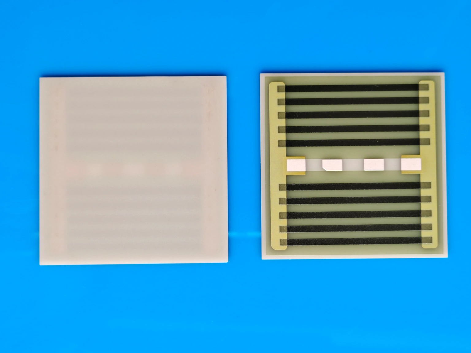
Identify whether the question concerns a broad heated plate, a narrow printed turn, a terminal joint or a small local anomaly. Record its physical dimensions and the neighboring surfaces that contribute radiation to the same view. A setup adequate for the plate average may not resolve the local feature controlling a design decision.
Distinguish the visible outline from the thermal target. A metal pad beside green overglaze can have a different apparent response even at the same temperature. Establish the radiometric treatment separately; this analysis asks whether the resulting target occupies enough resolved area to support a temperature measurement, not whether its visible color looks appropriate.
Calculate the projected pixel footprint
For a small instantaneous field-of-view angle, the projected size of one detector pixel is approximately working distance multiplied by that angle in radians. Use the lens-specific value and the actual object distance. For a larger field, camera optics and distortion may require a more complete mapping than a single center-field approximation.
With an illustrative IFOV of one milliradian at a distance of half a meter, the nominal projected pixel width is 0.5 millimeters. A 0.6 millimeter heater feature spans only about 1.2 pixels in that direction. At 0.2 meters it spans about three pixels, provided the lens can focus there. These are geometry examples, not specifications for a particular instrument.
s ≈ dθ; n ≈ w/s
- s is the nominal projected detector-pixel width at the target.
- d is working distance and θ is IFOV in radians for the selected lens.
- w is physical target width and n is its nominal pixel span.
Small-angle projection near the characterized field position. Nominal pixel span does not include the complete optical point-spread response or establish radiometric accuracy.
Do not treat one pixel as an isolated thermometer
Optical blur and detector response spread information across neighboring locations. A target occupying a nominal pixel can therefore contain substantial contribution from its surroundings. The camera's quantitative measurement footprint may require several pixels and additional margin, depending on the lens, focus, target contrast and required accuracy.
Use the manufacturer's applicable method and validate the installed setup rather than imposing one universal pixel-count rule. A general multi-pixel recommendation is a starting point, not proof that a narrow heater edge is fully measured. Digital enlargement changes the displayed size only; it does not recover radiation information that the optics never separated.
Focus at the heater plane, including the far edge
Focus on the surface being measured rather than a nearby fixture label or protective window. Record the focus setting and working distance. At close range, depth differences between the heater, terminals and support may become significant. A sharply visible fixture can coexist with a blurred printed surface.
For an oblique view, the projected footprint is stretched on the object and can vary across the field. Check the least-resolved consequential region, not only the center nearest the camera. Moving closer may improve pixel coverage while reducing field coverage or exceeding the lens's minimum focus distance; all of these constraints belong in the setup decision.
Use a controlled size-response or distance comparison
A suitable characterized thermal target can reveal how reported temperature changes as the target fills more of the measurement footprint. Keep target condition and surrounding radiation controlled while changing only the intended optical geometry. Use a target and method appropriate to the camera range; an arbitrary heated object is not a temperature standard.
On an actual heater, compare a stable identified feature at permitted distances while preserving electrical load, viewing angle and environment as closely as possible. A peak that rises as the feature occupies more resolved area suggests prior spatial averaging, but changing reflection or focus can also contribute. Retain the full setup record before assigning the difference to temperature.
Select a remedy from the limiting mechanism
A resolution problem needs an optical or measurement-boundary response. Increasing the color contrast can help locate an anomaly without making its reported temperature more accurate. Choose the next action according to what limits the actual target.
| Observed limitation | Useful action | What does not solve it |
|---|---|---|
| Feature spans too few nominal pixels | Reduce safe working distance or use suitable optics | Digital zoom or a larger monitor |
| Target has adequate span but is defocused | Refocus at the target plane and verify size response | Changing the palette |
| Far-edge feature is stretched or blurred | Review angle, depth and field coverage | Checking center focus alone |
| Mixed reflective and glazed surfaces share the footprint | Improve spatial separation and radiometric treatment | One emissivity setting for every surface |
| Required feature remains unresolved | Use another validated measurement route or report a bound | Presenting the displayed peak as the true local maximum |
Avoid linear temperature corrections for mixed pixels
A pixel receiving radiation from hot and cool regions does not generally report their area-weighted Celsius average. The detector responds within its spectral band and the camera converts radiance through its calibration and surface assumptions. A simple arithmetic correction based only on the estimated hot-area fraction is therefore not a defensible recovery of the true peak.
If a quantitative deconvolution or subpixel model is proposed, it needs validated optical response, geometry and radiometric assumptions, with uncertainty. That is a separate method development exercise. For routine review, improving resolution or using an independent suitable observation is usually more transparent than applying an unverified correction to an unresolved feature.
Document the feature-size envelope of the setup
Report the lens, distance, focus, angle, projected pixel size and size-response evidence with the thermal image. Name which features are quantitatively resolved and which are only visually localized. Preserve raw radiometric files and the original analysis region rather than only a rescaled screenshot.
Recheck the envelope after a lens change, increased working distance, protective-window addition or smaller heater revision. A camera's detector resolution stays constant while the object-space capability changes. The final claim should concern the specific feature and setup tested, not an unsupported statement that the camera can accurately measure every visible detail.
Send the heater feature and camera setup
The relevant dimensions are at the object, not on the display.
- Heater drawing with the smallest temperature-critical feature.
- Camera, lens, IFOV, working distance and focus range.
- Raw images, viewing angle and radiometric surface treatment.
- Stable-state records and available independent temperature observations.
The drawing-upload form loads as you reach this section.