
On this page
A low resistance reported for a ceramic via chain includes everything between its voltage-sense contacts. That may include face links, via-to-land transitions and terminal regions as well as vertical metallization. Subtracting a fixture value is justified only when that value represents the same excluded path. Moving the sense boundary on an unchanged specimen provides a direct way to test the attribution before reporting a resistance per via.
Measurement purpose
Identify the resistance spans supported by available sense contacts on an unchanged series via chain before removing access contributions.
Specimens and conditions
- Connectivity
- Identify both-face series routing, via count and accessible nodes; exclude alternate current paths.
- Stable test state
- Hold temperature, support and force contacts constant throughout each node comparison.
Equipment and records required
- Current source: Measure delivered current and maintain suitable compliance at non-damaging excitation.
- Voltage acquisition: Use high-impedance sense inputs with resolution and timing suitable for the smallest interval difference.
Method sequence
- Define
Draw force and sense boundaries and list unresolved internal terms.
Record: Node map and measurement equations.
- Measure
Acquire outer, inner and adjacent spans without changing the force path.
Record: Raw voltages, current and acquisition order.
- Check
Compare direct inner readings with telescoping differences and audit every correction.
Record: Consistency residual and correction uncertainty.
Decision and uncertainty
Report only resistance groups that the available observations identify; retain inaccessible contributions in the named group.
Include correlated calibration, drift, contact placement and subtraction sensitivity in the result.
The measurement engineer defines the supported boundary; the drawing owner decides whether it answers the acceptance requirement.
Traceable outputs
| Record | Required contents |
|---|---|
| Sense-boundary report | Node locations, included structures and direct or inferred span values. |
| Correction justification | Physical correspondence, sensitivity and limitations of any removed access contribution. |
Method review decisions
- Mark the force path and each sense-node pair separately on both faces.
- Use measured node differences to isolate accessible groups, not inaccessible individual interfaces.
- Reject a subtraction that depends on changed current distribution, temperature or contact geometry.
Name physical nodes along the complete series path
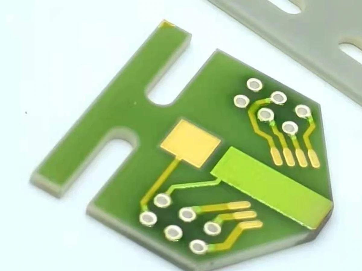
Assign consecutive electrical nodes to the chain from the entry land through each face link and vertical transition to the exit land. Record where a probe touches, whether the contact is on the printed land or an attached terminal, and which metallization lies between that point and the nearest via. A photograph needs an accompanying connectivity description when the back-face route is hidden.
Keep the force contacts outside the intended sense span. A Kelvin connection reduces external lead influence but does not remove material located inside the sensed region. The first deliverable is therefore a boundary drawing, not a corrected resistance number. Mark inaccessible boundaries explicitly so an omitted contact cannot silently become a supposedly measured quantity.
Move sensing without moving the excitation path
Apply the same controlled low-stress current while observing several high-impedance voltage pairs. The source connection, return connection, specimen support and temperature should remain unchanged. Sequential readings are suitable only when drift over the sequence is negligible or measured; otherwise simultaneous channels may be needed.
Changing the force contact can redistribute current across a wide land. A resulting voltage difference then combines a boundary change with a field change. Keep these as separate experiments. Confirm source compliance and record actual current for every voltage reading, because dividing all readings by a nominal setting can create false segment differences when contact resistance changes.
Use telescoping differences to isolate measured groups
Suppose nodes A, B, C and D occur in order on one unbranched path. With a common current, the resistance from A to D should equal the sum of A to B, B to C and C to D within uncertainty. This consistency check is valuable before assigning a central span to the vias. It can expose reversed polarity, a mistaken node or a changing acquisition state.
In a hypothetical measurement at one ampere, VAD is 8.4 millivolts, VAB is 1.1 millivolts and VCD is 1.3 millivolts. The inferred central resistance is 6.0 milliohms. A direct VBC measurement of 6.0 millivolts supports the boundary accounting. It does not prove that the central span contains only vertical via material.
RBC = RAD − RAB − RCD; RAD ≈ RAB + RBC + RCD
- RXY is the voltage between named nodes X and Y divided by their common test current.
- A and D are outer sense nodes; B and C define an accessible inner span.
- The example central span is 8.4 − 1.1 − 1.3 = 6.0 milliohms.
One stable unbranched ohmic path, consistent current and polarity, and negligible sense-input loading. Comparisons must include measurement uncertainty.
Do not divide an unresolved group into invented components
If the central span contains six vertical transitions and five face links, its measured resistance is the sum of both groups and their interfaces. Dividing by six gives resistance per transition group under a stated convention, not intrinsic resistance of an isolated via. Additional observations must genuinely separate the face links before a narrower interpretation is possible.
A symmetrical artwork does not demonstrate equal interface resistance. Without an independent node or validated physical model, several combinations of via and land resistance produce the same measured total. Preserve the combined quantity in the report rather than selecting a convenient assumed split. This distinction matters when a corrective action targets firing, land printing or probe access.
| Available span | Defensible result | Not established |
|---|---|---|
| Outer terminal to outer terminal | Total chain and included access resistance | Vertical metallization alone |
| Inner land to inner land | Central chain with remaining face links and interfaces | Separate land and via contributions |
| Individual accessible face link | Resistance of that link under the current boundary | All links have identical resistance |
| Individual vertical path with no bypass | That via-plus-interface span | Bulk material resistivity without geometry and interface knowledge |
Challenge the proposed fixture correction
A shorting coupon can characterize leads and some contacts, but it may not reproduce the product's surface, spreading resistance or pressure distribution. Compare exactly which elements remain inside the voltage span in both configurations. A correction for an external cable should not also be subtracted from a Kelvin reading that already excludes that cable.
Where access cannot be measured directly, treat the estimated correction and its uncertainty as a model input. Examine the consequence of using its upper and lower plausible values. A corrected result that becomes negative or changes strongly with a minor contact move is a warning about the boundary or model, not evidence of exceptionally conductive via material.
Evaluate uncertainty in small differences
Subtracting two large nearly equal values can leave a small difference with substantial relative uncertainty. Common current calibration errors may be correlated, while contact noise and time drift may not be. Keep these relationships when calculating the uncertainty of the inferred span instead of automatically adding every percentage in the same way.
Reverse current only with an approved low-stress method and stable contacts when thermoelectric offsets are relevant. Compare the polarity pair at corresponding thermal states. The reversal can help separate an offset from an ohmic voltage; it cannot correct an unidentified parallel path or prove that all buried segments have the same composition.
Use a failed node-sum check as diagnostic information
When the outer voltage does not match the sum of adjacent spans, first check node naming, polarity, actual current and acquisition timing. Inspect whether probes bridge neighboring conductors or whether input loading matters at a high-resistance interruption. Repeat the original sequence before reseating contacts so the as-found behavior is retained.
A consistent node sum with a localized increase points to the measured interval, not automatically to one hole. Record the smallest supported interval and its included features. Subsequent microscopy or sectioning can then target the right region under a separate investigation plan without overstating the electrical localization.
Release the result together with its electrical boundary
The measurement record should show the force connections, sense coordinates, current, temperature, raw voltage pairs and any correction. State whether the output is a total chain value, an accessible segment value or an average of unresolved transition groups. Include the direct-versus-inferred comparison and reasons for any excluded reading.
Repeat the boundary review when artwork, pad access or fixture contacts change. Do not transfer a subtraction solely because a revised coupon has the same number of holes. The purpose is to make each reported resistance traceable to what was actually observed, with a clear line between measurement, model and unresolved internal structure.
Provide the via-chain access drawing
Submit the electrical routing and proposed measurement connections together.
- Both-face chain artwork and identified accessible lands.
- Current, voltage pairs, temperature and acquisition order.
- Fixture short or correction method with its contact geometry.
- Required reported quantity and allowable investigation access.
The drawing-upload form loads as you reach this section.