
On this page
An alumina heater can fit its holder as a bare substrate and rock on a terminal after assembly. The ceramic outline has not changed, but the mounting interface has. Following the same part through its processing stages reveals whether fired deposits, joint protrusion or residue have become unintended support points.
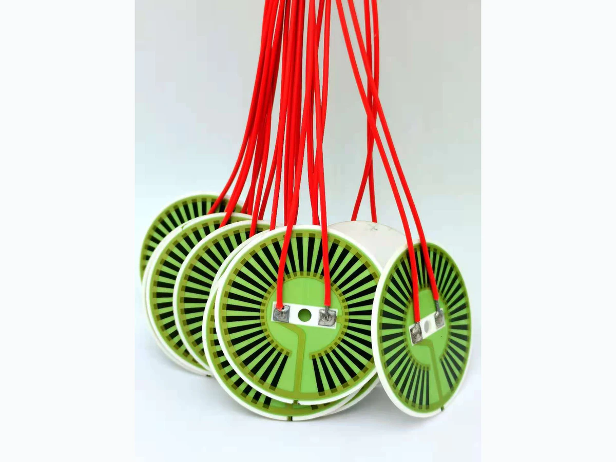
For a drawing-specific part, review the Custom thick film heaters construction, product evidence and quotation inputs alongside this method. Prepare the heater sizing worksheet with your operating conditions.
Key design decisions
- Identify which surface is allowed to seat and which finished features need relief.
- Check the terminal envelope after attachment and cooling, including its location relative to the seating datum.
- Use matched stage observations to distinguish permanent geometry change from removable contamination.
Mark the ceramic bearing surface before printing
Define the bearing surface on the bare alumina part and the matching surface in the holder. They may be a broad face, selected lands, or a perimeter outside the active circuit. A thickness dimension between ceramic faces does not establish the clearance available around a soldered terminal. The drawing needs both the structural seat and the space occupied by the completed electrical connection.
A print-free bearing region can still acquire paste from handling, an unintended edge deposit, or material transferred by a fixture. Inspect that region independently from conductor continuity. The seat is a functional interface: its cleanliness and form determine where mounting force enters the ceramic and where heat can leave it.
Retain the orientation of the part from incoming inspection onward. If a later rocking condition develops, an identified corner and face make it possible to compare the original surface with the finished assembly. Turning the part over between undocumented measurements destroys that useful connection even when every instrument reading is individually valid.
Follow the seat through the complete firing sequence
Each printed layer changes the local surface envelope, and subsequent firing can change the condition of material deposited earlier. The sequence matters where a conductor wraps near an edge, a protective layer approaches the bearing land, or a backside pattern shares the mounting face. Inspect after the actual last thermal operation that can affect the seat, rather than assuming the first satisfactory fired measurement remains final. Use the named paste system and its documented compatible layers; neither the ceramic label nor a nominal furnace peak establishes how an unspecified deposit behaves. A thin fired feature may be electrically necessary but mechanically unacceptable as a concentrated support. That conflict is resolved through a deliberate relief or revised bearing definition, not by tightening the holder until the part appears flat.
Measure the attached terminal as a three-dimensional feature
A terminal drawing often gives pad position and lead direction while leaving the joint envelope implicit. The completed envelope includes the lead or tab, solder or adhesive, fillet, insulation sleeve and any reinforced transition. Local joint height can exceed the thickness of the metal tab itself. A generous electrical pad therefore does not guarantee mechanical clearance inside a shallow holder.
Measure protrusion from the same seating datum used by the mount. Include the region that the terminal can occupy after its permitted alignment variation and after the harness is connected. The external lead should not be used to force the heater into position. Where the termination is intentionally compliant, preserve its free movement rather than clamping the compliant section inside a pocket that defeats its function.
Calculate the pocket clearance at the terminal location
Use a local clearance stack to decide whether the holder relief remains open under the finished assembly. Combine the smallest pocket depth with the largest terminal protrusion and the unfavorable relative seating variation. The latter can include measured local lift or the drawing's allowed relative position, but each term must refer to the same axis and datum. Do not add full part flatness twice if it is already included in the terminal protrusion measurement.
For a hypothetical assembly, take a pocket depth of 0.80 mm with a 0.05 mm negative allowance, a maximum terminal protrusion of 0.55 mm, and an additional unfavorable local seating variation of 0.08 mm. The remaining clearance is 0.12 mm. This positive result only means the declared envelope fits geometrically. It does not provide insulation clearance, allowable bending, or a guarantee against contact during cable movement. Those requirements require their own physical boundaries.
g_min = d_pocket,min − h_terminal,max − z_relative,max
- g_min: minimum calculated normal gap in millimeters.
- d_pocket,min: shallowest permitted relief depth measured from the holder seat.
- h_terminal,max: finished protrusion from the heater's corresponding seating datum.
- z_relative,max: additional unfavorable relative displacement not already contained in the other terms.
Worst-direction linear dimensional stack at one location. Contact deformation and dynamic lead movement are excluded and must be considered separately.
Check the geometry after the attachment fixture is removed
The termination may be held in place while solder solidifies or an adhesive develops strength. Releasing that fixture can reveal springback, tilt or a load that the fixture had temporarily carried. Cooling can also change relative position because the metal termination and ceramic do not contract identically. Inspect the cooled, unrestrained assembly before assessing it in the holder. If the joint is satisfactory only while an assembly clamp remains engaged, the fixture has concealed a functional mismatch. A compliant lead can accommodate some relative motion, but its shape, free length and later cable anchoring determine whether that compliance remains available. An apparently large solder fillet can stiffen the transition and shift load into the pad edge. Record the actual connection geometry before deciding whether a pocket-depth change alone will solve the seating issue.
Use stage witnesses to locate the first seating change
Keep a small set of identified specimens through the same sequence and inspect the same bearing locations. Start with unprinted ceramic, continue after the final firing, then after terminal attachment, cleaning and harness routing. At each stage, record what has changed physically. The objective is to locate the first operation that changes seating, not simply to accumulate final dimensions.
A removable particulate high point behaves differently from permanent bow. If cleaning removes the rocking, retain a description or image of the removed material and investigate how it reached the bearing surface. If the rocking remains, compare measured form and terminal envelope. Do not repeatedly rub the seat clean before recording the original condition.
Use a handling control when a delicate feature could be damaged by the inspection itself. A witness part passed through the same measurement and remounting sequence without the process change can reveal that problem. Contact force during measurement should be small enough not to flatten the feature under investigation.
| First observed change | Feature to inspect | Useful discrimination |
|---|---|---|
| After firing | Bearing land, edge deposits, backside layers | Permanent surface envelope versus loose transfer residue |
| After attachment | Fillet height, terminal tilt, cooled lead shape | Joint protrusion versus changed ceramic form |
| After cleaning | Residue on seat or in holder relief | Cleaning deposit versus preexisting protrusion |
| After cable routing | Lead restraint and connector position | Harness load versus static pocket mismatch |
Separate rocking, thermal gaps and ceramic damage
Rocking that disappears when the terminal is placed over an open relief suggests that the connection has become a support point. A repeatable local hot region away from the terminal may instead indicate poor contact elsewhere on the bearing face. Fracture beside a terminal can arise when a clamp forces the ceramic down around a protruding joint. These observations guide inspection, but none independently proves a single cause.
Correlate the physical witness with powered behavior only after the mechanical assembly is within its reviewed envelope. Forcing contact through additional clamp force can suppress a thermal symptom while increasing bending. Record resistance before and after mounting under matched temperature conditions. A permanent shift or intermittent connection during seating warrants stopping the mechanical comparison and preserving the specimen for joint and ceramic inspection.
Verify the finished seat with the production holder
Use the intended holder material, relief geometry, bearing finish and load application sequence. Measure the completed terminal clearance and confirm that assembly force reaches the intended ceramic lands. Repeat the fit after the representative heating and cooling sequence, because a room-temperature trial does not reveal all relative movement. Document fixture substitutions and access openings used for inspection; they can change stiffness or contact.
The resulting manufacturing definition should connect the last relevant firing, attachment geometry, cleaning state and holder drawing. If a new terminal, additional protective layer or altered cable route is introduced, revisit the local clearance stack and stage witnesses. This keeps a fit decision tied to the finished heater rather than to a bare ceramic sample that no longer represents the interface delivered to the equipment assembly.
Send the finished seating and terminal envelope
Mounting review needs the surfaces that carry force after every layer and connection is present.
- Alumina and holder drawings identifying bearing lands, relief pockets, finished datums and normal gap requirements.
- Layer order, print keepouts, final firing sequence and any backside or edge features near the seat.
- Terminal material, joining process, cooled protrusion measurements, fixture release and final harness routing.
- Stage-linked rocking, form, resistance and thermal observations with the original residue or failure location preserved.
The drawing-upload form loads as you reach this section.