
On this page
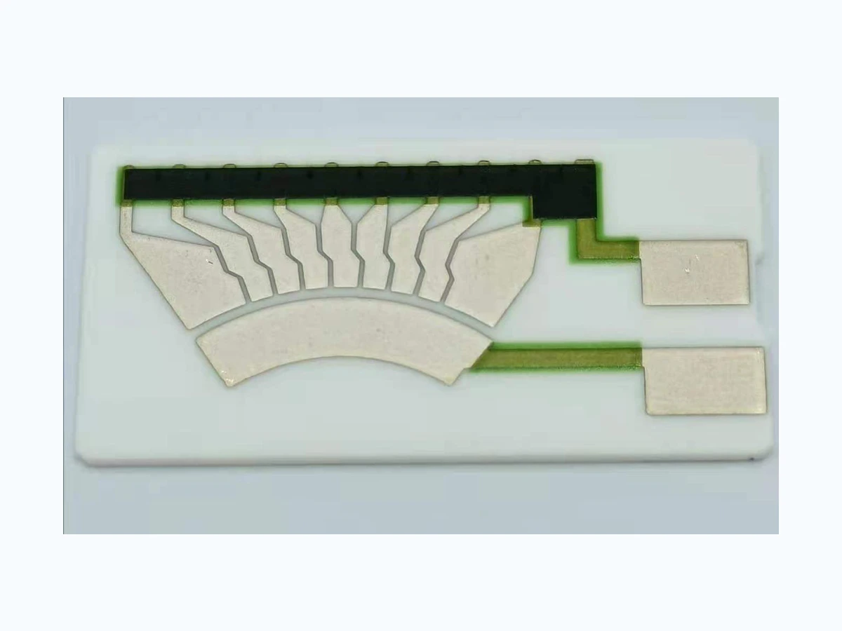
A fuel sender begins with a rotating arm whose pivot is fixed to the housing. The card does not see liquid height directly; it sees the location at which a carrier presents the wiper to the printed path. Establish the pivot center, arm zero direction and installed gravity direction before using an electrical trace.
For a drawing-specific part, review the Fuel level sensor resistor card construction, product evidence and quotation inputs alongside this method. Prepare the curve and error worksheet with your operating conditions.
Key design decisions
- Start at the float pivot, not at the printed curve.
- Transform arm angle into a card coordinate.
- Use angular sensitivity to set measurement spacing.
Start at the float pivot, not at the printed curve
A fuel sender begins with a rotating arm whose pivot is fixed to the housing. The card does not see liquid height directly; it sees the location at which a carrier presents the wiper to the printed path. Establish the pivot center, arm zero direction and installed gravity direction before using an electrical trace. Measure the effective distance from pivot to the point that drives the carrier rather than assuming the visible arm length is the lever radius. A slot, bent tab or offset follower can make the effective radius change with angle. Record clockwise and counter-clockwise travel separately because clearance and elastic preload may place the follower on different sides of the same nominal geometry.
Transform arm angle into a card coordinate
Represent the linkage as a sequence of coordinate transforms from the housing frame to the arm, follower and card. For a direct tangential contact, a first screen is xw = x0 + r sin(theta + phi), with x0 locating the card, r the effective lever radius and phi the clocking angle. A radial component may also matter when the wiper follows an arc rather than a straight track. Use the actual follower constraint to decide which component controls contact. Plot predicted contact-center position against arm angle and overlay the complete footprint width. The footprint edge, not only its center, determines whether conductive segments, resistor material and protected end regions remain engaged.
xw = x0 + r sin(theta + phi)
- xw: wiper-center coordinate in the card frame
- x0: card offset at the declared angular zero
- r: effective drive radius of the reviewed linkage
- theta: measured arm angle
- phi: installed clocking offset
Rigid single-radius linkage with a defined contact projection; slots, flexure, backlash and changing effective radius require a geometry-specific transform.
Use angular sensitivity to set measurement spacing
Different parts of the arc have different travel per degree because dxw/dtheta = r cos(theta + phi). As an example only, a 42 mm radius at a local cosine of 0.93 gives about 0.68 mm travel for one degree. If the contact footprint is 1.4 mm wide, a one-degree sampling interval can skip a region comparable with half the footprint. The same interval becomes less sensitive near a geometric extremum. Select angle stations from the steepest local derivative and the required electrical resolution. Keep radians in the derivative calculation, then label plotted angles in the customer convention. This numerical exercise describes sensitivity; it is not a claim about a supplied sender.
Treat approach direction as part of the mapping
A linkage with clearance does not have one unique position at a commanded angle. Approach a station from the fill direction, record angle and contact coordinate, move beyond it, then return from the drain direction. The gap between the two wiper positions is a local lost-motion band. Repeat the sequence after several full strokes so the result is not merely initial seating. If the arm angle repeats while contact position changes, inspect the carrier, slot and wiper mounting. If both coordinates move together, examine the pivot or fixture reference. Do not average the branches before determining whether the receiver uses one direction preferentially or must tolerate both.
Establish mechanical, contact and electrical endpoints in order
List the events that occur at each travel end: housing stop contact, float interference, carrier stop, footprint entry into the end extension, signal saturation and possible loss of continuity. Their order must be intentional. An electrical plateau can be useful when overtravel is allowed, but it can also hide mechanical motion that the system owner expects to observe. A wiper center inside the artwork is not enough if part of the footprint crosses an unprotected ceramic edge. Build an overlay using stop tolerances, card location, print registration and footprint size. Evaluate the low and high ends independently because the same clocking error consumes reserve at one end while adding it at the other.
Observe angle and wiper location at the same instant
A calibration rig should capture arm angle and contact coordinate synchronously. Encoder counts at the drive motor are insufficient when a coupling or gear lies between that encoder and the pivot. Use an independent observation at the arm or shaft and a position method that resolves the wiper footprint without changing its force path. At several stations, collect stationary repeats, repeated approaches, full sweeps and complete remounts. Compare those variance components separately. A stable electrical trace with an uncertain mechanical coordinate cannot validate kinematics, while a precise coordinate paired with a heavily loaded voltage measurement cannot validate the printed transfer.
Separate three common mapping faults
Interpret errors by their coordinate signature. A nearly constant wiper-position offset suggests card placement or clocking. An error that changes smoothly with angle suggests an incorrect lever radius, projection or effective linkage geometry. A gap between opposite approaches indicates lost motion or frictional seating. Local discontinuity with stable mechanical coordinates moves the investigation toward contact or printed features. Preserve raw pairs rather than only fitted coefficients, because a polynomial can absorb a local mechanism fault and still report a small overall residual.
| Pattern | Likely boundary to inspect | Confirming comparison |
|---|---|---|
| Constant coordinate offset | Card location or angular zero | Remount card and re-establish pivot zero |
| Slope error through most travel | Effective arm radius or projection | Measure linkage geometry and compare local derivative |
| Direction-dependent separation | Follower clearance, flex or friction | Approach identical stations from both directions |
| Local electrical step only | Contact or printed transition | Hold mechanical position and repeat electrical observation |
Release a kinematic map with explicit ownership
The controlled package should include the tank and sender orientation, pivot definition, arm and follower dimensions, card datums, track artwork, wiper footprint, both stop stacks and measured angle-position pairs. State whether the released function maps arm angle to contact center, footprint edge or electrical output. Keep the later resistance and controller conversion in linked records rather than merging them invisibly into the linkage model. Recalculate after a pivot, arm length, follower, stop, wiper or card-locator change. For quotation, provide the desired level or angle points, allowed mapping error, operating directions and the evidence format required by the system owner. Final tank indication and vehicle-level qualification remain outside a component-only conclusion.
Send the float-arm angle to wiper-position mapping inputs
Provide the as-built shape, circuit and validation traces needed to examination tank-referenced float-arm angle against sliding contact geometric coordinate on the resistor card.
- tank design definition, pivot and arm feature dimensions, quantified angle-position pairs, sliding contact physical footprint, travel motion direction and output requirement
- Governing permitted variations and raw observations for pivot offset, arm flex and wiper-carrier play.
- Definition of a common angular datum at the pivot housing, motion or exposure stage order, fixture and receiver circuit load.
- Allowed functional error, validation ownership, unresolved assumptions and specified technical basis format.
The drawing-upload form loads as you reach this section.