
On this page
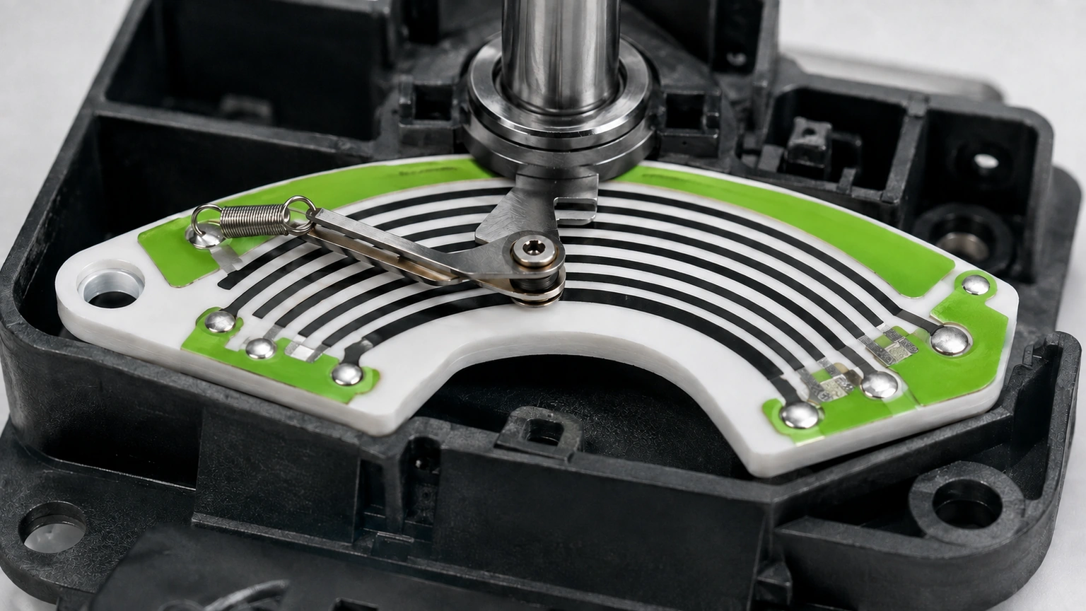
Electrical-gap versus heater-pitch model is evaluated on the actual adjacent heater traces, fired conductor edges, supply nodes, inactive gaps and served load footprint. The review distinguishes electric-field path across the fired gap from thermal pitch controlling heat-source spacing, and uses separate gap and pitch metrics as its traceable decision output. One geometric spacing must not serve two models: insulation follows the gap, while temperature uniformity follows source pitch.
Key design decisions
- Freeze the as-built definition of adjacent heater traces, fired conductor edges, supply nodes, inactive gaps and served load footprint.
- Discriminate electric-field path across the fired gap from thermal pitch controlling heat-source spacing through separate gap and pitch metrics.
- Revalidate the affected evidence when trace width, fired gap, voltage nodes, coating, environment or load contact changes.
Failure mechanisms and discriminating evidence
The first diagnostic signature is electrical stress localized at the minimum fired gap; map it against the expected action of electric-field path across the fired gap. Temperature banding that follows source pitch without leakage evidence should be separated because it points to thermal pitch controlling heat-source spacing. Electrical-gap versus heater-pitch model covers the represented adjacent heater traces, fired conductor edges, supply nodes, inactive gaps and served load footprint only; similarity of names does not prove separate gap and pitch metrics equivalence.
Begin electrical-gap versus heater-pitch model diagnosis at the earliest separate gap and pitch metrics divergence and correlate it with adjacent heater traces, fired conductor edges, supply nodes, inactive gaps and served load footprint genealogy. Challenge electric-field path across the fired gap while holding thermal pitch controlling heat-source spacing within a documented band. A missing separate gap and pitch metrics input leaves electrical-gap versus heater-pitch model conditional until evidence for adjacent heater traces, fired conductor edges, supply nodes, inactive gaps and served load footprint is supplied. Correct the evidenced electrical-gap versus heater-pitch model mechanism rather than compensating elsewhere.
| Observation | Interpretation under test | Discriminating action | Disposition boundary |
|---|---|---|---|
| electrical stress localized at the minimum fired gap | electric-field path across the fired gap | Challenge electric-field path across the fired gap under a controlled comparison | Hold the represented configuration |
| temperature banding that follows source pitch without leakage evidence | thermal pitch controlling heat-source spacing | Vary thermal pitch controlling heat-source spacing independently | Separate the competing explanation |
| Unstable separate gap and pitch metrics | Measurement-chain problem | Check reference, setup and raw acquisition | Repeat only after cause review |
| Consistent separate gap and pitch metrics | Bounded agreement | Confirm on reserved adjacent heater traces, fired conductor edges, supply nodes, inactive gaps and served load footprint specimens | Release represented state only |
Validation of electrical-gap versus heater-pitch model
Plan confirmation around the real adjacent heater traces, fired conductor edges, supply nodes, inactive gaps and served load footprint boundary, including the loading or process step linked to electric-field path across the fired gap. Include a bounded thermal pitch controlling heat-source spacing condition; without it, separate gap and pitch metrics cannot discriminate the competing electrical-gap versus heater-pitch model explanation. Preserve adjacent heater traces, fired conductor edges, supply nodes, inactive gaps and served load footprint before cleaning or teardown, because the electric-field path across the fired gap evidence may otherwise be lost.
Acceptance logic, invalid-run criteria and retest rules are frozen before the confirmation separate gap and pitch metrics traces are opened. For electrical-gap versus heater-pitch model, a adjacent heater traces, fired conductor edges, supply nodes, inactive gaps and served load footprint surrogate must disclose omitted features and demonstrate that they do not control separate gap and pitch metrics. A missing separate gap and pitch metrics input leaves electrical-gap versus heater-pitch model conditional until evidence for adjacent heater traces, fired conductor edges, supply nodes, inactive gaps and served load footprint is supplied. Contradictory evidence reopens the electric-field path across the fired gap model.
Release boundary and revalidation triggers
Configuration release requires an auditable chain from the current drawing through adjacent heater traces, fired conductor edges, supply nodes, inactive gaps and served load footprint genealogy to the raw separate gap and pitch metrics record. List every adjacent heater traces, fired conductor edges, supply nodes, inactive gaps and served load footprint configuration outside the accepted separate gap and pitch metrics evidence. Preserve adjacent heater traces, fired conductor edges, supply nodes, inactive gaps and served load footprint before cleaning or teardown, because the electric-field path across the fired gap evidence may otherwise be lost.
Configuration control flags trace width, fired gap, voltage nodes, coating, environment or load contact as a electrical-gap versus heater-pitch model trigger requiring renewed engineering review. The electrical-gap versus heater-pitch model change review identifies surviving separate gap and pitch metrics evidence, then names the electric-field path across the fired gap calculation, measurement or confirmation needing repetition. For electrical-gap versus heater-pitch model, photographs locate electric-field path across the fired gap; measurement of separate gap and pitch metrics establishes its magnitude and distribution. Unknown adjacent heater traces, fired conductor edges, supply nodes, inactive gaps and served load footprint values remain unresolved.
RFQ preparation for electrical-gap versus heater-pitch model
The RFQ package begins with the controlled definition of adjacent heater traces, fired conductor edges, supply nodes, inactive gaps and served load footprint and the material, interface, process and operating information needed for electrical-gap versus heater-pitch model. Include source measurements for separate gap and pitch metrics, the conditions governing electric-field path across the fired gap, the alternative influence from thermal pitch controlling heat-source spacing, and the intended quantity. A missing separate gap and pitch metrics input leaves electrical-gap versus heater-pitch model conditional until evidence for adjacent heater traces, fired conductor edges, supply nodes, inactive gaps and served load footprint is supplied.
Provide original separate gap and pitch metrics files and the electrical-gap versus heater-pitch model reference state. Describe planned trace width, fired gap, voltage nodes, coating, environment or load contact revisions, unresolved adjacent heater traces, fired conductor edges, supply nodes, inactive gaps and served load footprint inputs and acceptance ownership. Application review chooses the electric-field path across the fired gap comparison without inventing capability data. Challenge thermal pitch controlling heat-source spacing with an independent reference while holding the electric-field path across the fired gap condition stable for electrical-gap versus heater-pitch model.
Engineering decision for electrical-gap versus heater-pitch model
Before calculations begin, identify the exact adjacent heater traces, fired conductor edges, supply nodes, inactive gaps and served load footprint that owns the decision and the conditions under which it was observed. The analysis compares the expected signature of electric-field path across the fired gap with the competing signature of thermal pitch controlling heat-source spacing using separate gap and pitch metrics as the observable. For electrical-gap versus heater-pitch model, photographs locate electric-field path across the fired gap; measurement of separate gap and pitch metrics establishes its magnitude and distribution. One geometric spacing must not serve two models: insulation follows the gap, while temperature uniformity follows source pitch.
Any change to trace width, fired gap, voltage nodes, coating, environment or load contact creates a new review state and requires the affected evidence to be reconsidered. Preserve adjacent heater traces, fired conductor edges, supply nodes, inactive gaps and served load footprint before cleaning or teardown, because the electric-field path across the fired gap evidence may otherwise be lost. For electrical-gap versus heater-pitch model, report separate gap and pitch metrics with specimen identity, coherent units and the adjacent heater traces, fired conductor edges, supply nodes, inactive gaps and served load footprint operating state; include uncertainty.
Physical model and competing influences
Map adjacent heater traces, fired conductor edges, supply nodes, inactive gaps and served load footprint after processing, then relate its datums, boundaries, interfaces and measurement points directly to separate gap and pitch metrics. Document electric-field path across the fired gap history while keeping the thermal pitch controlling heat-source spacing operating and geometric variables separate in electrical-gap versus heater-pitch model. Arithmetic illustrating electrical-gap versus heater-pitch model declares no limit for electric-field path across the fired gap and no production capability for adjacent heater traces, fired conductor edges, supply nodes, inactive gaps and served load footprint.
Trace how electric-field path across the fired gap propagates through adjacent heater traces, fired conductor edges, supply nodes, inactive gaps and served load footprint to change separate gap and pitch metrics. Model thermal pitch controlling heat-source spacing separately because the two electrical-gap versus heater-pitch model paths may interact rather than add independently. For electrical-gap versus heater-pitch model, photographs locate electric-field path across the fired gap; measurement of separate gap and pitch metrics establishes its magnitude and distribution. Arithmetic illustrating electrical-gap versus heater-pitch model declares no limit for electric-field path across the fired gap and no production capability for adjacent heater traces, fired conductor edges, supply nodes, inactive gaps and served load footprint.
Bounded calculation for separate gap and pitch metrics
The electrical-gap versus heater-pitch model worksheet evaluates p_heat = W_trace + g_electric; nominal dimensions cannot be mixed with another adjacent heater traces, fired conductor edges, supply nodes, inactive gaps and served load footprint specimen. Carry bounded electric-field path across the fired gap cases; a separate electrical-gap versus heater-pitch model case set isolates thermal pitch controlling heat-source spacing. For electrical-gap versus heater-pitch model, photographs locate electric-field path across the fired gap; measurement of separate gap and pitch metrics establishes its magnitude and distribution.
A 0.8 mm fired trace beside a 0.5 mm gap gives 1.3 mm heating pitch, while the electrical gap remains 0.5 mm. In electrical-gap versus heater-pitch model, this separate gap and pitch metrics arithmetic checks units and sensitivity; acceptance stays with the adjacent heater traces, fired conductor edges, supply nodes, inactive gaps and served load footprint drawing and application review. Preserve adjacent heater traces, fired conductor edges, supply nodes, inactive gaps and served load footprint before cleaning or teardown, because the electric-field path across the fired gap evidence may otherwise be lost.
p_heat = W_trace + g_electric
- separate gap and pitch metrics: defined result for electrical-gap versus heater-pitch model
- electric-field path across the fired gap: influence evaluated from controlled adjacent heater traces, fired conductor edges, supply nodes, inactive gaps and served load footprint inputs
- thermal pitch controlling heat-source spacing: competing influence retained in the electrical-gap versus heater-pitch model model
For electrical-gap versus heater-pitch model, use only the identified adjacent heater traces, fired conductor edges, supply nodes, inactive gaps and served load footprint, coherent units, a declared separate gap and pitch metrics reference state and traceable bounds.
Measurement and sampling plan
The separate gap and pitch metrics observation chain records adjacent heater traces, fired conductor edges, supply nodes, inactive gaps and served load footprint sensor location, loading, bandwidth, filtering and synchronization. The electrical-gap versus heater-pitch model sampling plan distinguishes instrument repeats, repeated setups and independent adjacent heater traces, fired conductor edges, supply nodes, inactive gaps and served load footprint specimens. Locate the first separate gap and pitch metrics divergence, then compare its timing with the electric-field path across the fired gap history on adjacent heater traces, fired conductor edges, supply nodes, inactive gaps and served load footprint.
Collect separate gap and pitch metrics at positions or records that expose electric-field path across the fired gap; convenient access to adjacent heater traces, fired conductor edges, supply nodes, inactive gaps and served load footprint alone does not define the sample. Preserve raw electrical-gap versus heater-pitch model values, acquisition timing, setup changes and reference checks. Electrical-gap versus heater-pitch model covers the represented adjacent heater traces, fired conductor edges, supply nodes, inactive gaps and served load footprint only; similarity of names does not prove separate gap and pitch metrics equivalence. Preserve adjacent heater traces, fired conductor edges, supply nodes, inactive gaps and served load footprint before cleaning or teardown, because the electric-field path across the fired gap evidence may otherwise be lost.
Project inputs for electrical-gap versus heater-pitch model
Send the controlled adjacent heater traces, fired conductor edges, supply nodes, inactive gaps and served load footprint information required to evaluate separate gap and pitch metrics.
- For electrical-gap versus heater-pitch model: current drawing, finished adjacent heater traces, fired conductor edges, supply nodes, inactive gaps and served load footprint geometry, material stack and interfaces.
- For separate gap and pitch metrics: the adjacent heater traces, fired conductor edges, supply nodes, inactive gaps and served load footprint process sequence, raw evidence and reference state.
- For the mechanism comparison: bounded electric-field path across the fired gap and thermal pitch controlling heat-source spacing values.
- For electrical-gap versus heater-pitch model review: quantity, separate gap and pitch metrics failure consequence, validation owner and unresolved questions.
The drawing-upload form loads as you reach this section.