
On this page
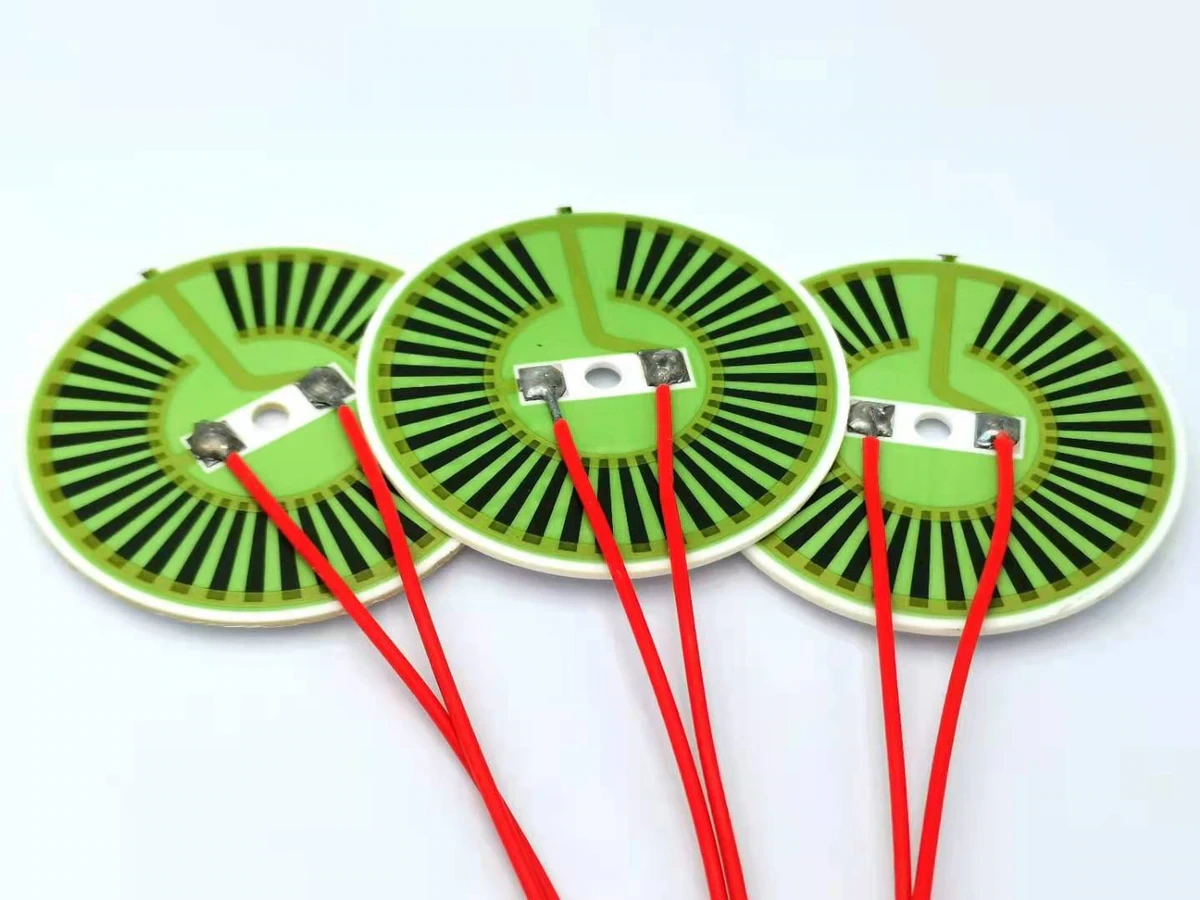
A terminal cold zone is an intentionally nonheated connection region, but it is not necessarily cold in operation. Heat can arrive from the active heater, from resistive loss in the connection or from nearby equipment. The design must keep the electrical joint and cable within their own limits while maintaining useful heating where the process needs it. This requires a thermal path and a mechanical load path, not merely a blank strip in the artwork.
Key design decisions
- Specify terminal and cable temperatures separately from active-area temperature.
- Reserve an inactive connection region with a defined route for heat and mechanical load.
- Measure joint heating under current as well as heat conducted from the active heater.
Define what the cold zone protects
List the components that occupy the connection region: pad, solder or other joining material, lead, insulation, adhesive, reinforcement and nearby housing. Each can have a different temperature or mechanical limit. The cold zone should be sized to protect the controlling element of this actual stack, not an assumed generic connector.
Show where the active resistor stops and where conductors carry current into the terminal. A conductor may dissipate less heat than the resistor but still warm if it is narrow, poorly connected or subjected to high current. Treat the term cold as a design intention that must be measured, not as a guarantee created by omitting resistive material.
Map heat arriving from the active region
Heat spreads from the active heater toward its terminal region through the substrate, conductors and attached protective layers. The distance, section area, material and mounting determine the temperature gradient. A metal tab or cable can remove heat from the joint, but it may carry that heat toward another temperature-sensitive component.
Review the final cable route and enclosure. A test cable draped into cool open air can provide a heat sink that will not exist inside the equipment. Conversely, a cable routed beside a hot surface can warm the joint from the outside. Both effects should be included when choosing the inactive region and the location of temperature observations.
Separate connection loss from conducted heat
Measure or bound the resistance of the connection path at the intended current. A small resistance can still create significant local heating when current is high. The relevant location may be a solder joint, crimp, interface or narrow conductor segment rather than the visible pad surface.
A four-wire measurement can help separate a low-resistance region from test-lead effects when the geometry allows appropriate sensing. Compare voltage drop and temperature at matched current. If the joint temperature rises disproportionately while the active heater condition remains similar, investigate contact quality and local resistance rather than simply extending the cold zone. Preserve the connection condition during the measurement so probing does not improve an otherwise poor contact.
P_joint = I² R_joint; V_joint = I R_joint
- I: current through the joint under the stated operating mode.
- R_joint: resistance of the defined connection region, excluding unrelated test leads.
- P_joint: electrical heat generated inside that region.
The relation treats the connection as resistive at the measured operating condition. Temperature-dependent contact behavior and intermittent faults require time-resolved observations.
Allocate space for both heat and assembly
Reserve a connection area that permits joining, inspection, cable routing and strain relief without covering the active pattern. Keep mechanical restraints on regions designed to carry them. A short inactive strip may be electrically convenient but provide little distance for a useful thermal gradient or for a robust cable transition.
A larger cold zone consumes heating area and may alter the load-temperature distribution near the edge. Review that trade explicitly. The objective is not the largest possible blank margin; it is a connection region that remains within limits while preserving the required useful heated area. The drawing should identify both boundaries so one team cannot enlarge a pad into a region another team expects to heat uniformly.
Choose a correction from the measured mechanism
Different terminal-temperature problems call for different actions. A connection heated by its own resistance needs an electrical or joining correction. A sound joint heated mainly by substrate conduction may need a changed thermal path or location. A cable that pulls on the joint needs mechanical relief even if its temperature is acceptable.
Use observations that can separate these mechanisms. Record joint voltage drop, current, local temperatures and cable route together. Change one feature at a time in a controlled comparison. This avoids reducing a thermal symptom by adding a large cable heat sink while leaving an unstable electrical interface or damaging mechanical load untouched.
| Observed symptom | Mechanism to investigate | Useful next comparison |
|---|---|---|
| Joint heats strongly when current increases | Connection resistance or a narrow current path. | Measure the defined joint voltage drop and compare joining condition at matched current. |
| Joint remains hot after heater power is reduced | Heat stored in or conducted from nearby structures. | Log substrate, support and cable temperatures during cooling. |
| Terminal temperature changes with cable routing | Cable heat sinking or external heat pickup. | Repeat with the intended enclosure route and controlled restraint. |
| Electrical continuity changes when the cable moves | Mechanical load or an intermittent interface. | Inspect strain relief and monitor the connection without flexing the active heater. |
Monitor the joint rather than an unrelated nearby surface
Choose temperature observations close enough to represent the vulnerable material without materially changing the connection. A sensor attached to a large pad may not capture the hottest internal contact. Infrared readings can also be distorted by emissivity differences between metal, solder and protective coating. Use a method suited to the geometry and uncertainty requirement.
Record startup, sustained operation, shutdown and the relevant duty-cycle transitions. The active region and terminal may peak at different times because their thermal masses and heat paths differ. A single end-of-test reading can therefore miss the controlling condition. Repeated assembly measurements are useful where cable attachment or contact variation is expected.
Write separate terminal and active-area requirements
The completed specification should name the maximum permitted temperatures at the joint, cable insulation and any controlling adhesive or reinforcement. Keep them separate from the useful load-temperature requirement and active-area maximum. State mounting, cable route, current and time condition for the measurements.
Link the terminal drawing to joining and inspection requirements so later material or cable changes receive the correct review. A replacement lead with the same electrical resistance can have different thermal conduction or stiffness. A new connector position can also alter both heat flow and strain. The cold-zone design remains valid only while those important interfaces stay within the evaluated envelope.
Send the terminal stack and installed cable route
A terminal-zone review needs the electrical joint, thermal environment and mechanical restraint shown together.
- Active-area and terminal drawing, pad and conductor dimensions, joining material and the proposed lead or connector construction.
- Current range, connection resistance or voltage-drop observations, startup mode and expected electrical duty.
- Temperature limits for joint, wire insulation, adhesive and reinforcement, with the intended load and enclosure conditions.
- Cable route, strain relief, nearby heat sinks or hot surfaces and synchronized terminal and heater-temperature records.
The drawing-upload form loads as you reach this section.