
On this page
trace routing around boundaries opens at the controlled thermal load, not at a material label. Engineering ownership extends across fired trace centerline, width and obstacle map, including their interfaces. The experiment must distinguish current crowding at turns and necks from local heat sinking around holes or clamps. The decision record explains how segment resistance and two-dimensional temperature selects among candidates. The canonical intent is limited to trace routing around boundaries. General product selection remains and include the existing heater family content. This calculation releases neither a temperature value limit nor a reliability promise. A proposed hole, setback, fired width, turn radius or clamp zone cannot be treated as an approved production envelope.
Key design decisions
- Define fired trace centerline, width and obstacle map at the as-built scope.
- Apply segment resistance and two-dimensional temperature to separate current crowding at turns and necks from local heat sinking around holes or clamps.
- Revalidate after any consequential change to hole, setback, fired width, turn radius or clamp zone.
Bounded calculation for segment resistance and two-dimensional temperature
The review relation, R_segment = R_sheet L_eff / W_eff, exposes the governing quantified terms. Define every symbol from synchronized readings on the same specimen. Bound the calculation across credible local heat sinking around holes or clamps states. A correct engineering method expression does not authorize an unsupported manufacturing limit.
The worked case illustrates input handling for trace routing around boundaries. The illustrative source values are not a documented heater construction. Recalculate at credible limit cases, then determine what controls segment resistance and two-dimensional temperature. With 40 ohm/square, a 12 mm effective run and 1.5 mm fired width gives 320 ohms before end effects.
R_segment = R_sheet L_eff / W_eff
- segment resistance and two-dimensional temperature: calculated or captured output at the defined test state
- current crowding at turns and necks: principal material effect kept configuration-controlled
- local heat sinking around holes or clamps: separate boundary included in sensitivity review
Apply only for trace routing around boundaries together with compatible unit system, sample identity, timing, and measurement scope.
Geometry and operating inputs
Draw fired trace centerline, width and obstacle map at the measured case. Identify every opening, joint, support, probe point, and neighboring heat sink. The engineering method relies on as-built form while preserving its source artwork provenance. Relate each location to the recorded segment resistance and two-dimensional temperature.
Work from one time base for power, thermal reading, mating load state, and controller action events. Do not mix a transient peak together with a stabilized value under one label. A room-case photograph cannot substitute for a measurement of current crowding at turns and necks. Specify the initial electrical and thermal test state for trace routing around boundaries.
Decision boundary for trace routing around boundaries
trace routing around boundaries is anchored to the controlled thermal load, not at a material label. The decision exercises fired trace centerline, width and obstacle map at one recorded configuration. Evaluate current crowding at turns and necks separately while local heat sinking around holes or clamps is retained. Selection evidence is the observed segment resistance and two-dimensional temperature, using confidence limit.
The heater overview continues to own broad construction and commercial context. The method does not prove a production article rating, service life, or manufacturing range. Drawing review remains necessary when hole, setback, fired width, turn radius or clamp zone is unknown. The engineering question remains specifically trace routing around boundaries.
Failure discrimination
A supportable failure route in trace routing around boundaries is hot inner radius at a sharp turn. The expected pattern must follow the mechanistic distribution of current crowding at turns and necks. An alternative pattern is, a cold island caused by routing too far from a sink boundary directs attention toward local heat sinking around holes or clamps. Similar endpoint measurements can conceal two mechanisms requiring separate fixes.
Preserve scenario snapshots before support condition, after installed operating point, during power, and after recovery. Document contact surfaces prior to cleaning, separation, or reprocessing. Do not average away evidence that challenges the current causal path. Diagnosis starts at the first captured divergence in segment resistance and two-dimensional temperature.
| Evidence | Causal path to test | Discriminator | Disposition |
|---|---|---|---|
| hot inner radius at a sharp turn | current crowding at turns and necks | Controlled change in current crowding at turns and necks | Hold affected construction |
| a cold island caused by routing too far from a sink boundary | local heat sinking around holes or clamps | Substitute or map local heat sinking around holes or clamps | Hold trace redesign |
| Unstable segment resistance and two-dimensional temperature | Measurement chain | Reference check and raw trace | Repeat valid comparison |
| Confirmed bounded response | trace routing around boundaries | Reserved specimens | Release represented envelope only |
Measurement and controls
Test equipment selection follows the physical definition of segment resistance and two-dimensional temperature. Retain verification or working range checks, mapped resolution, loading, timing, and readings treatment. Electrical measurements require terminal definition, lead effects, settling, and loading checks. Unrecoverable readings are marked rather than replaced by a convenient average.
A stable sample exposed to measurement-chain change reveals test artifacts. Do not count multiple readings on one build as separate production data. Hold back material so the final trace routing around boundaries rule is evaluated without retuning. Apply paired articles that differ mainly in current crowding at turns and necks.
Mounted-system validation
Exercise the trace routing around boundaries method on the intended fired trace centerline, width and obstacle map. Represent the actual waveform plus the decision boundary state that challenges trace routing around boundaries. A convenient block cannot stand in for the controlled load unless current crowding at turns and necks remains comparable. List every difference between the test article and final assembly, especially local heat sinking around holes or clamps.
Verification sensitivity to current crowding at turns and necks and specificity using respect to local heat sinking around holes or clamps. Capture why any run is invalid and whether replacement testing is authorized. When reserved disagrees, investigate the omitted trace routing around boundaries term. Define data-quality and engineering acceptance decision logic before reviewing the holdback cohort.
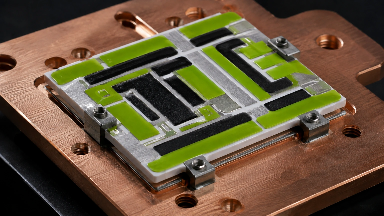
Trace routing around an aperture should be reviewed by segment, because equal total resistance does not guarantee equal local heating. Record fired width, thickness, corner radius, distance to the cut edge, conductor overlap, and the thermal mass on both sides of each turn. Estimate segment resistance from the measured geometry, then compare the predicted power allocation with a temperature map referenced to the same coordinates. A narrow neck, abrupt turn, or termination transition can create a local peak even when the overall heater reaches its target resistance. If the hole diameter, edge clearance, paste system, fired geometry, mounting contact, or drive waveform changes, repeat the segment calculation and the mapped mounted test before reusing the earlier routing conclusion.
Prepare an engineering RFQ
Provide mechanical and thermal interfaces relevant to trace routing around boundaries. Provide the source, wiring, energization sequence, sensor definition, and turn-off logic. Project observed terms must bound current crowding at turns and necks and local heat sinking around holes or clamps. Unknowns remain conditional until drawing and application review resolve them.
The trace routing around boundaries package carries the reproducible worksheet and all supporting documents. The accepted decision applies only across the recorded data boundary. Reopen review whenever hole, setback, fired width, turn radius or clamp zone shifts. A documented trace routing around boundaries record identifies shape record, specified materials, interfaces, controls, and instruments.
Configuration and change control
The controlled package binds construction version to electrical, thermal, mechanical, and measurement boundaries. Attach the R_segment = R_sheet L_eff / W_eff worksheet, input provenance, measurement uncertainty treatment, direct segment resistance and two-dimensional temperature measurements, and disposition. Do not imply coverage for a as-built form or duty that was not represented. Revalidation is required after a material change in hole, setback, fired width, turn radius or clamp zone.
The heater overview continues to own broad construction and commercial context. No thermal reading, lifetime, tolerance, dielectric, or uniformity rating follows from this method. An unsupported hole, setback, fired width, turn radius or clamp zone retains the conclusion conditional. Content ownership stops at the trace routing around boundaries decision.
Provide inputs for trace routing around boundaries
Send the controlled drawing and operating limit needed to evaluate segment resistance and two-dimensional temperature.
- Drawing, observed dimensions, layer identities, electrical terminations, instrumentation elements, and fired trace centerline, width and obstacle map.
- Drive supply, cold and operating quantified resistance, applied potential, current, drive profile, controller action, and wiring.
- Thermal load, contact, mounting arrangement, service environment, current crowding at turns and necks, and local heat sinking around holes or clamps.
- Required segment resistance and two-dimensional temperature, failure functional effect, verification plan, requested volume, observations, and change owner.
The drawing-upload form loads as you reach this section.