
On this page
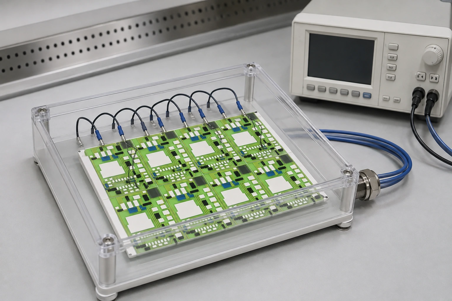
A humidity-bias measurement combines an environmental exposure with an electrical measurement. A falling insulation resistance can reflect moisture-dependent surface conduction, contamination, a developing conductive path or leakage in the fixture itself. The behavior during exposure and the behavior after drying are both useful, but neither should be interpreted without the voltage history, specimen condition and measurement boundaries.
Key design decisions
- Define the electrode path and the bias and measurement voltages separately.
- Measure fixture leakage and settling behavior under the same environment.
- Keep in-exposure data distinct from recovery readings after removal or drying.
Define the insulation path being measured
Identify the two electrodes and the material or surface between them. A printed ceramic circuit can contain exposed ceramic, glass overglaze, conductor edges, attachment residues and terminal insulation within the measured path. A measurement across that assembly does not automatically isolate the bulk dielectric property of one layer.
Draw the electrode geometry, separation, surface route and any guard arrangement. Record which areas are coated or glazed and where boundaries end near conductors. Keep the actual processed specimen geometry in the record. Differences in edge coverage or contamination location can change the measured path even when the nominal substrate material is the same.
Control humidity and condensation as different conditions
Record chamber temperature and humidity together with specimen temperature where it affects condensation risk. A surface colder than the surrounding air can experience condensation under conditions that cannot be understood from the chamber humidity display alone. Opening the chamber or transferring a specimen can also change its surface condition quickly.
Decide whether the method is intended to produce a noncondensing humid exposure or a controlled condensation event. Do not treat an accidental droplet as an ordinary variation of the former. Document transitions, stabilization and any visible moisture, because a sudden leakage event may be tied to the environmental transition rather than to the elapsed exposure time.
Separate exposure bias from the measurement sequence
The voltage applied during environmental exposure may differ from the voltage used to read insulation resistance. Record both, including polarity, duration, switching intervals and any interruptions. Electrical bias can influence the specimen state, so a measurement is not always a passive observation of an unchanged surface.
Choose voltage and acceptance criteria from the selected method and application requirements. Increasing voltage to obtain a larger current signal can change the mechanism under study. If the instrument reaches compliance or a protective limit, retain that event in the record. A clipped current value should not be converted into an exact resistance as though the commanded voltage remained across the specimen.
Establish the measurement system floor
Humidity can reduce insulation in cables, feedthroughs, supports and connectors as well as in the specimen. Measure an appropriate blank or fixture configuration under the same environmental sequence to establish its contribution. The instrument's dry laboratory specification does not describe the complete high-humidity measurement system.
Use guarding where appropriate to reduce unwanted leakage paths, and distinguish it from shielding against external electrical interference. Guard geometry must preserve the intended specimen path rather than diverting the current that the test is supposed to measure. Follow instrument safety and connection requirements, especially when accessible parts can be at bias or guard potential.
Distinguish settling from sustained conduction
After a voltage change, the measured current can include capacitive charging and dielectric absorption as well as conduction. Record current versus time long enough to apply a defined reading rule. A single early reading may overstate leakage, while an overly long delay can miss short events relevant to the circuit's operation.
Keep switching transients and channel order in multi-specimen measurements visible. Repeatedly switching between channels can create a different electrical history from continuous monitoring. If only periodic measurements are available, state the interval and recognize that brief events between readings may not be captured.
| Observation | Possible explanation | Discriminating check |
|---|---|---|
| Current decays after every voltage step | Charging or absorption contribution | Compare defined settling windows and the time trace |
| Blank fixture and specimens rise together | Environmental leakage in the measurement system | Inspect guarded fixtures and feedthroughs |
| Current follows condensation events | Surface moisture changes the conduction path | Correlate specimen temperature and environmental transition |
| Brief large current excursions | Intermittent conductive path or switching artifact | Review synchronized voltage and channel-switch records |
| Leakage remains elevated after controlled recovery | Persistent contamination or material damage | Repeat under defined dry conditions and inspect the path |
Treat recovery as a separate measurement phase
Specify how the specimen is removed, conditioned and measured after exposure. Time, temperature, humidity, bias state and handling can all affect the recovery curve. A reading immediately after removal and one after extended drying are different results, not competing versions of the same measurement.
Recovery can help distinguish a moisture-dependent reversible contribution from a persistent change, but apparent recovery does not prove that no damaging event occurred. A temporary conductive bridge can disappear, and a damaged path can become less conductive when dry. Preserve the in-exposure current trace and inspect the relevant locations before cleaning or applying a restorative process.
Separate leakage from a specific failure mechanism
A low insulation-resistance value is an electrical observation. It does not alone identify electrochemical migration, dielectric breakdown or bulk moisture absorption. Use location-specific visual or microscopic evidence and the voltage-environment history to evaluate the proposed mechanism. If a conductive feature is suspected, preserve its polarity and orientation information.
Compare specimens with controlled differences in cleaning, glaze coverage, electrode spacing or attachment process when investigating cause. Change one principal factor at a time where practical. An arbitrary mixture of altered voltage, humidity and geometry can create a different failure mechanism and make the comparison difficult to use for a production decision.
Report a time-dependent insulation result
Present the current or resistance history with the applied voltage, environmental conditions and measurement rule. Mark interruptions, compliance events, fixture checks and the transition into recovery. Keep individual specimens visible; a lot average can hide one circuit with repeated short-duration leakage events.
Connect the result to the circuit function and applicable acceptance criteria. Some applications are sensitive to small leakage long before a permanent short develops, while others are concerned with isolation under defined conditions. The test report should state which requirement was evaluated and what the data show under that method, enabling a focused improvement in surface control, geometry or insulation construction.
Define a humidity-bias measurement
Provide the electrode path, environment and circuit sensitivity so exposure, measurement and recovery can be separated in the test plan.
- Electrode geometry, conductor material and glaze or coating boundaries.
- Exposure temperature, humidity or condensation sequence.
- Bias voltage, polarity, measurement voltage and channel timing.
- Fixture, guarding, instrument range and blank-system measurements.
- Circuit leakage requirement, recovery conditions and available current traces.
The drawing-upload form loads as you reach this section.