
On this page
A polyimide printed heater must remain electrically and mechanically stable while it is mounted into the final shape. Flexibility of the base film does not mean every resistor, conductor, adhesive or lead joint can tolerate the same bending. The layout should identify where heat is generated, where the laminate may flex and where cable loads are transferred to the equipment. This separation is especially important when a heater is wrapped onto a curved part or folded during assembly.
Key design decisions
- Separate installation bending from repeated flexing in service.
- Place bends and cable restraints using the actual laminated construction and material data.
- Qualify the mounting adhesive and heat-transfer interface independently from the polyimide film.
Identify the flexible-heater construction
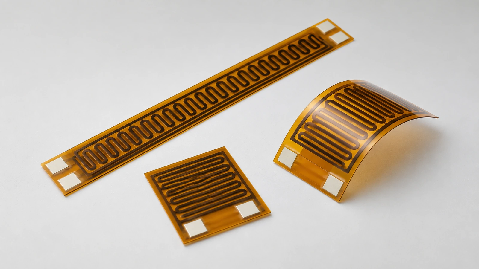
Polyimide is a substrate or insulating film used in several heater technologies. A printed resistive layer, an etched metal foil and a wire element are different constructions even if each appears inside an amber flexible laminate. Their bend behavior, resistance-temperature relation and processing conditions should not be interchanged.
Describe the complete stack including protective films, adhesive layers, resistor, conductors and terminal reinforcement. Record the orientation of the live layer relative to the mounted surface. Etched-foil and printed-ink heaters have different constructions; bend and temperature limits must come from the selected stack, not from a different product route. Use the selected construction’s own data for the final bend and temperature requirements.
Reserve bend regions before routing the resistor
Show every planned bend on the mechanical layout, including its direction and installation sequence. Avoid placing a sharp fold through a resistor transition or terminal joint. A region intended to flex can be kept electrically inactive or routed with a construction specifically evaluated for the required movement.
The relevant strain depends on the distance of a layer from the laminate’s neutral region and on the bend curvature. Layer thicknesses and stiffnesses therefore matter as well as the total film thickness. Do not assign a universal bend radius from the appearance of a sample. A design that survives one gentle installation bend may still fail under repeated motion or under a bend imposed while hot.
Separate fixed installation from dynamic flexing
A heater bonded once around a stationary cylinder experiences a different duty from a heater crossing a moving hinge. Define the number and type of movements, whether bending reverses direction, and whether the movement occurs at operating temperature. Cable vibration can also repeatedly load a nominally fixed lead exit.
For dynamic service, identify the strain-bearing region and how the heater is supported on either side. A stiff termination next to an unsupported flexible section can concentrate strain at the boundary. The test sequence should reproduce that boundary rather than bending an unmounted strip in free air. Record electrical continuity during movement when intermittent faults are plausible, not only after the specimen is laid flat.
Transfer cable loads away from the electrical joint
Lead wires should be restrained so handling, vibration and connector forces do not pull directly on the printed terminal. A reinforcement can spread mechanical load, but an abrupt stiffness change may create a new bend concentration at its edge. Show the transition and the intended route of the cable in the installation drawing.
Consider the cable’s temperature as well as its mechanical load. A lead exiting a hot region may carry heat toward a connector or allow external heat to reach an adhesive joint. Strain relief should not cover an active resistor region and trap heat unintentionally. The final routing needs clearance from sharp metal edges and moving parts without relying on the heater laminate as protective cable insulation.
Select the adhesive for the actual environment
An attachment adhesive determines contact, thermal resistance and the mechanical restraint applied to the heater. Its permitted temperature and environmental exposure may differ from those of the polyimide film. The bond also depends on the receiving surface, preparation, curvature and the applied assembly procedure.
Evaluate whether the adhesive must accommodate differential expansion, moisture, cleaning chemicals or repeated heating. Use the intended surface finish and contamination control during testing. A bond that looks complete immediately after assembly may contain air pockets or lose contact during operation. Specify how those defects will be detected and whether the installation allows inspection, repair or replacement rather than assuming adhesion is permanent.
| Region | Primary function | Failure to prevent |
|---|---|---|
| Active resistor region | Deliver heat through a controlled contact area | Local overheating caused by an air pocket or unsupported segment. |
| Inactive bend zone | Accommodate the specified curvature and movement | Cracked printed material at a fold or repeated-flex location. |
| Reinforced lead exit | Distribute handling force into the supported laminate | A concentrated load that peels or fractures the terminal joint. |
| Adhesive-to-load interface | Maintain repeatable thermal and mechanical contact | Debonding or trapped air that changes the temperature distribution. |
Check temperature in the mounted shape
The installed curvature changes contact area, airflow and proximity to neighboring parts. A flat-bench test may therefore miss the hottest region of a wrapped heater. The active region should remain supported as intended, particularly near the seam, edges and lead exit where the geometry is least uniform.
Measure power at the heater terminals and temperatures at the load, active pattern, adhesive-sensitive regions and lead attachment. At the same electrical input, a lifted edge can become hotter because it loses the designed heat path into the load. Reducing power may conceal the symptom while leaving poor contact unresolved. Correct the interface and repeat the thermal comparison before changing the printed pattern.
Test the installation sequence as well as operation
Follow the real assembly sequence using the intended tools, release liner handling, bend direction and cable restraint. Record resistance and visual condition before forming, after forming, after bonding and after the selected thermal exposure. These checkpoints help identify when a change first appears.
Use specimens that represent the most demanding permitted geometry rather than only a generous-radius sample. Inspect terminal transitions and laminate edges closely. If resistance changes only during bending, investigate an intermittent conductor or connection before concluding that the resistive material has drifted. Repeat the final mounted condition after a controlled disassembly only when that operation is part of the intended service process; otherwise it introduces a different load case.
Make the mounting instructions reproducible
A useful installation package shows orientation, allowable bend regions, cable route, attachment surface and the sequence in which restraints are secured. It identifies which areas may be handled and which must not be creased, stretched or pressed by an assembly tool. Such instructions are part of the electrical reliability strategy, not merely packaging notes.
Link them to the actual heater revision and adhesive specification. If the receiving part changes from flat to curved, if a cable connector moves, or if the assembly begins to flex during use, revisit the design. The original polymer-film label does not establish suitability for a new mechanical or thermal boundary.
Send the installed shape and lead-exit details
A flexible printed-heater review should begin with the mounted geometry and the motion it must survive.
- Laminate construction, available material data, active-pattern area, overall outline and the side intended to contact the heated load.
- Bend directions and radii, installation sequence, fixed or repeated-flex duty and the temperatures at which movement occurs.
- Lead-wire specification, terminal reinforcement, connector location, cable restraint and expected handling or vibration loads.
- Receiving-surface material and finish, adhesive requirements, environmental exposure, target temperatures and planned continuity or thermal checks.
The drawing-upload form loads as you reach this section.