
On this page
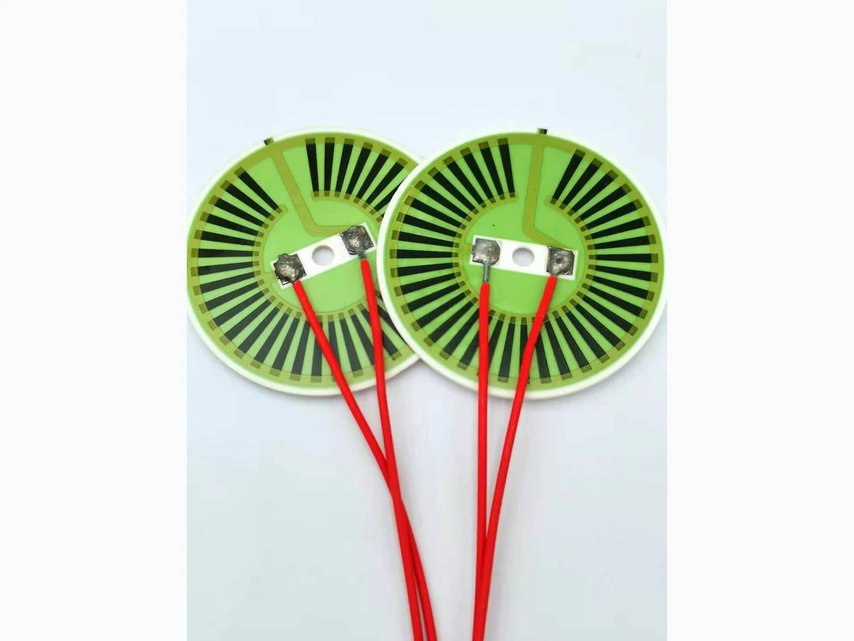
A ring heater has two thermal boundaries: an outer perimeter and an inner opening. The inner edge may face air, contact a shaft or surround a flowing process, so its heat loss can differ greatly from the outer edge. A radial design review should establish those boundaries before allocating electrical heat across the annulus. The ring outline alone does not establish a uniform temperature or a suitable conductor and resistor layout.
Key design decisions
- Model the inner and outer boundaries separately.
- State whether electrical power density refers to the annular envelope or actual resistive area.
- Measure radial profiles at more than one angular position.
Identify what touches the inside and outside
Draw the ring in its installed condition. Include the opening, any sleeve or shaft, outer support, clamping surfaces, terminal region and the load receiving heat. An inner opening exposed to still air is very different from an opening tightly fitted around a cold metal tube. The same applies to an outer rim that is free in one fixture and clamped in another.
Note whether contact varies around the circumference. A cable exit, locating key or split clamp can break rotational symmetry. A purely radial model is a useful starting point only if the geometry, power distribution and boundary conditions are sufficiently uniform in angle. Mark deviations explicitly so the measurement plan can test the assumption.
Use the annular area without hiding inactive regions
For an annular envelope, area follows from the difference between the outer and inner circular areas. This is a geometric denominator, not automatically the area that generates heat. Terminal pads, a routing interruption, mounting features and inactive margins reduce the usable electrical region. Identify their areas separately.
A narrow annulus can have a high perimeter-to-area ratio, making boundary losses important compared with a solid plate of similar outer size. Enlarging the hole changes both the active area and the inner boundary length. A comparison based only on outer diameter therefore misses two major changes at once. Keep geometry and power-area definitions together in calculations.
A_annulus = π(r_o² − r_i²); q_envelope = P/A_annulus
- r_o and r_i: outer and inner radii expressed in the same length unit.
- P: electrical power delivered to the defined heater region.
- q_envelope: average power per annular envelope area, not local resistor power density.
The expression assumes a circular annular envelope. Openings, terminals and unheated regions must be subtracted or reported separately when evaluating the electrical active area.
Distinguish radial spreading from heat crossing the plate
Heat can move across the ring thickness into a contacting load and radially toward either perimeter. These paths act simultaneously. A narrow band with broad face contact may transfer most useful heat through thickness, while a ring heating an inner sleeve may depend strongly on radial flow. The preferred trace allocation is different in those cases.
Use a thermal network or a spatial model that includes the intended load contact. A one-dimensional radial conduction expression should not be applied to a face-heated assembly without checking whether it represents the dominant path. The purpose of the first model is to identify which distances, thicknesses and contacts control the temperature gradient, not to give a precise-looking answer from an unsuitable simplification.
Measure radius and angle together
Choose radial measurement lines that cross the annulus from inner to outer edge. Repeat them at multiple angular positions, including the terminal sector and regions adjacent to clamps or interrupted traces. This makes it possible to distinguish a radial boundary effect from an angular feature in the electrical pattern or installation.
Place measurements near, but not ambiguously on, material edges. An infrared pixel mixing the hot ring and a cool opening can understate the edge temperature. A contact sensor can also bridge an edge and create its own conductive path. Record spot size, attachment and exact location. The useful result is a temperature profile tied to physical coordinates, not just a color band around the hole.
Use the shape of the profile to choose the next test
Different radial profiles point to different investigations. The interpretation should remain a hypothesis until electrical input, sensor behavior and contact conditions have been checked. Compare the same locations through startup and steady operation because the inside and outside hardware may warm at different rates.
When changing one boundary, retain the same mounting orientation and electrical mode. Otherwise a controller power adjustment or a changed cable heat path can obscure the reason for the new profile. The most efficient development test changes one physically meaningful condition and examines the corresponding region of the map.
| Observed pattern | Boundary or layout question | Focused comparison |
|---|---|---|
| Inner edge stays cooler at all angles | Is the opening coupled to a cool sleeve or fluid? | Measure that inner load and compare its contact or flow at unchanged heater power. |
| Only the terminal sector is cooler | Do leads or inactive pads remove heat locally? | Compare angular profiles and measure terminal metal and cable temperatures. |
| Outer edge changes with clamp position | Is outer support contact uneven? | Repeat with documented clamp orientation and controlled support contact. |
| One narrow radius is much hotter | Does local heat generation or a face-contact gap concentrate temperature? | Align the profile with resistor artwork and independently inspect the contact interface. |
Review the conductor route around the opening
A ring geometry can force conductor and resistor paths to change direction or pass through narrow sectors. Check the electrical path separately from the thermal outline. Equal radial spacing of visible traces does not guarantee equal current density or equal heat generation, particularly near terminal transitions and turns.
The layout should leave clear insulation distances and defined inactive regions around the opening where required. Do not compensate a thermal deficit by crowding conductors into a mechanically constrained sector without reviewing electrical and manufacturing margins. A local increase in resistor power may help at one mounting condition and produce a hot spot when the inner load is removed. Evaluate the full intended boundary range.
Write a ring-specific thermal requirement
State the useful annular zone, any excluded terminal sector and the allowed radial or angular variation. Include the inner load, outer support, face contact, electrical input and time condition. If temperature is specified only at one radius, make clear that it does not establish uniformity across the full ring width.
Retain the measurement geometry with the final drawing so later changes to hole size, clamp position or cable route trigger the right review. Where the installed ring may experience loss of contact or loss of fluid flow, include that abnormal boundary in the equipment-level protection assessment. A successful nominal map is not a substitute for understanding what happens when the dominant heat-removal path changes.
Provide the inner and outer thermal interfaces
A ring-heater review requires the annular geometry and the distinct loads connected to both perimeters.
- Inner and outer diameters, thickness, terminal sector, inactive regions and the intended resistor or conductor artwork.
- Inner sleeve, shaft or fluid condition; outer support and clamp arrangement; and face-contact material and area.
- Useful annular temperature zone, radial or angular uniformity requirement, allowed peak temperature and startup conditions.
- Voltage and current limits, sensor locations, coordinate-based thermal profiles and any measurements after changing inner or outer contact.
The drawing-upload form loads as you reach this section.