
On this page
- Fill the Image Before Demanding Release
- Create Controlled Contact at the Squeegee
- Let the Screen Separate Cleanly
- Allow Paste to Recover After Shear
- Support Registration and Repeatability
- A Worked Engineering Review
- Design Review Checklist
- Questions Engineers Commonly Ask
- Related Engineering Resources
- Closing Note
Prepared by Chipsimple Engineering Team, Engineering and technical content review
Published online August 10, 2026 · Reviewed August 10, 2026
ENGINEERING ARTICLE 13 / VOLUME 3
How Thick Film Screen Printing Actually Transfers a Circuit Pattern
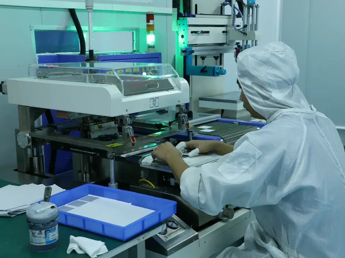
During the print stroke, the squeegee brings the patterned screen toward the ceramic and drives paste into the open image. Behind the blade, screen tension and snap-off separate the mesh from the deposited film. Paste rheology then determines whether the image holds its edges or slumps. Understanding that sequence explains why more pressure is rarely a universal cure.

Fill the Image Before Demanding Release
A useful way to frame the decision is this: Open mesh must contain a consistent paste volume before the pattern can transfer. As a result, incomplete filling causes skips while excessive flooding can smear or dry into the image. That cause-and-effect chain should remain visible when thick film screen printing process is reviewed with purchasing and quality teams.
The manufacturing boundary is protected when the team can set flood and print strokes for the paste and image density. This approach separates the customer's functional need from the supplier's machine-specific compensation.
Confirm the decision with consecutive print inspection and deposit-mass tracking. Include both typical and boundary-condition specimens where the failure consequence justifies them.
The symptom alternating light and heavy prints across a production run deserves a structured investigation. Check material lot, artwork position, thermal history and measurement setup before assigning a single cause.
Create Controlled Contact at the Squeegee
Geometry and material meet at this point: The blade locally deflects the screen and applies shear to the paste. Therefore, pressure, speed, angle and blade condition change flow and screen wear. A nominal specification that omits the interface is incomplete even if every individual value looks reasonable.
During release, use the lowest stable settings that produce complete transfer. Make sure the acceptance method measures the same physical feature that the design calculation assumed.
Useful confirmation includes print geometry across the image and blade-wear records. Keep photographs or sections tied to part, revision, lot and orientation so they remain evidence rather than decoration.
One failure signature is good centre transfer with distorted edges or progressive image growth. It often becomes clear only when results are sorted by position, process stage or exposure instead of being combined into one average.
Let the Screen Separate Cleanly
Process capability follows from the mechanism: Screen tension and snap-off create release behind the moving blade. The direct implication is that poor release lifts paste, smears edges or leaves mesh marks. This makes the topic a design input, not merely a factory setting adjusted after the drawing is complete.
A practical release action is to qualify tension, off-contact and support for the ceramic thickness. The requirement should survive staff changes and future lot reviews because it is recorded with the controlled construction.
Use edge and surface inspection in print direction to demonstrate margin. When feasible, compare the result before and after the operation most likely to disturb it.
Pay attention to tails, double images or directional roughness. A corrective action is credible only when it changes that physical mechanism and the follow-up data confirm the change.
Allow Paste to Recover After Shear
Thixotropic paste should flow under the blade and regain body after transfer. The consequence is that recovery rate controls levelling, edge retention and screen clearing. In a thick film screen printing process review, this relationship deserves an explicit decision rather than an assumption copied from a previous drawing.
The practical control is to condition paste and control temperature, dwell and open time. That instruction should be linked to the layer, material system or feature it governs so that production and inspection read it in the same way.
Verification should include line width and film profile at defined times after printing. If the evidence is collected only after final assembly, the team loses the ability to separate printing, firing, trimming and assembly effects.
A common warning sign is geometry that changes between the first and last substrate. Treat that symptom as a request to examine the process chain, not simply as a reason to widen the final tolerance.
Support Registration and Repeatability
Substrate location, flatness and tooling establish the coordinate system for every layer. The consequence is practical: small fixture variation becomes overlap loss in multilayer or resistor termination features. This is one reason thick film screen printing process cannot be reduced to a single catalogue value.
During design review, use stable datums, vacuum or support and verified screen alignment. The objective is not to freeze every process setting on the customer drawing, but to define the functional boundary that the manufacturer must protect.
A useful evidence package contains fiducial registration data across the run. Comparing those records with the approved construction is more informative than judging an isolated photograph or one resistance reading.
Watch for a consistent layer shift that varies with substrate orientation. It often indicates that two individually acceptable variables have combined at the edge of their windows.
A Worked Engineering Review
A narrow conductor shows ragged edges and occasional gaps. Rather than increasing pressure, first confirm screen cleanliness and paste conditioning. Print a short series while recording deposit mass. If mass is stable but edges deteriorate with dwell, paste drying at the screen is likely. If the defect follows print direction, inspect blade edge and release. If it follows substrate position, check support and flatness. Fired sheet resistance then confirms whether the wet-print correction produced the required conductor, not merely a better photograph.
Design Review Checklist
- Control flood and print strokes.
- Record blade speed, pressure, angle and condition.
- Verify tension and snap-off.
- Condition paste and manage open time.
- Measure registration and deposit across the run.
Questions Engineers Commonly Ask
Does higher squeegee pressure produce a thicker print?
Not reliably. It can force contact and alter paste transfer, but thickness is mainly governed by screen geometry, paste and release. Excess pressure can distort the image.
Why does the first print differ from later prints?
Screen filling, paste conditioning and dwell may not yet be stable. Define a controlled start-up and verification sequence.
Can a good wet print still fire badly?
Yes. Drying, burnout, paste compatibility and furnace profile determine the fired result.
Related Engineering Resources
Closing Note
Stable screen printing comes from controlling fill, shear, contact, release and recovery. When those events are measured, print defects become diagnosable instead of being chased by pressure adjustments.