
Overview
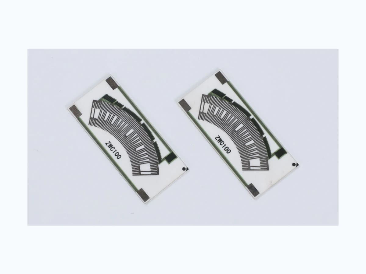
A dual-track accelerator-pedal sensor is a system architecture, not merely two printed resistor paths placed beside each other. The pedal mechanism, return springs, shafts, wipers or noncontact elements, track laws, electrical supply, signal conditioning, controller diagnostics, connector, harness, calibration, environmental sealing, and vehicle response must work together. This guide defines the inputs needed to evaluate two resistive tracks and their relationship while keeping the safety decision with the vehicle and electronic-control owner. It does not prescribe a universal voltage ratio, slope, tolerance, diagnostic threshold, safe state, or fault reaction. Those values depend on the selected architecture, hazard analysis, controller design, legal requirements, and representative vehicle validation. The visible resistor-card photograph is component context only and is not evidence of a released pedal assembly.
Failure controls
These are review prompts, not evidence that every risk applies or that every test is available.
- A
Two tracks can share a wiper carrier, connector, reference, ground, substrate, linkage, or controller path, so channel count alone does not establish independence.
- B
A ratio that looks correct at endpoints can leave an undetected disagreement or nonlinear error between calibration points.
- C
Contact wear, debris, vibration, or fluid exposure can create intermittent events that averaging or slow logging hides.
- D
Changing filtering or sample timing can alter plausibility diagnostics even when the printed geometry remains unchanged.
- E
FMVSS 124 addresses accelerator-control return behavior within its jurisdiction and scope; it does not define every electronic pedal diagnostic or prove global compliance.
- F
A component photograph or bench sweep cannot demonstrate vehicle torque response, hazard control, driver warning, or safe-state suitability.
Dual-track pedal validation sequence
The order makes assumptions and ownership visible before a result is promoted to a requirement.
- 01
Define the pedal system boundary
Draw the pedal, pivot or translation, return mechanisms, stops, sensor housing, rotor or slider, wipers, tracks, connector, harness, controller inputs, power and ground, throttle or torque command path, and vehicle response. Mark which elements are shared between channels and which are genuinely independent.
- 02
Specify both transfer laws
Provide mechanical travel against each raw electrical output, including nominal slope, offsets, ratio or inverse relationship, dead zones, diagnostic windows, hysteresis, independent linearity, noise, resolution, and timing. Distinguish an intentional nonlinear law from an error relative to an assumed straight line.
- 03
Allocate variation and wear
Budget track print, trim, wiper contact, mounting datum, shaft or linkage play, connector and harness resistance, supply and reference variation, ADC error, temperature, humidity, contamination, wear, and aging. State whether limits apply to each channel, their correlation, or the resulting interpreted pedal position.
- 04
Design diagnostics around faults
List open and short circuits, shorts to supply or ground, cross-channel shorts, contact intermittency, stuck outputs, implausible ratio, shared reference loss, delayed channel, connector fretting, mechanical jam, spring or linkage fault, and controller failure. Assign detection time, permitted response, driver indication, data retention, and recovery behavior.
- 05
Validate mechanism and electronics together
Exercise the intended pedal mechanics, sensor card, wiper, housing, seal, connector, harness, supply, controller input, filtering, sampling, diagnostics, and software. Synchronize travel, force, both raw signals, interpreted position, faults, and response across temperature, vibration, humidity, fluids, endurance, and permitted abnormal conditions.
- 06
Control calibration and changes
Tie calibration points, limits, diagnostic thresholds, fixtures, software, mechanical datums, wiper load, track revision, connector, and test scripts to released records. Reassess evidence after changes to the track law, pedal leverage, housing, return system, electronics, filtering, or fault strategy.
Engineering review matrix
Each row links a design variable to evidence that can support a drawing or release decision.
| Variable | Control question | Verification route |
|---|---|---|
| Mechanical travel law | How do pedal angle or displacement, leverage, stops, free play, hysteresis, return force, and sensor movement relate? | Measure synchronized pedal travel, sensor travel, force, and both outputs across directions, rates, temperatures, wear states, and tolerances. |
| Channel relationship | Are outputs proportional, inverse, offset, staged, or otherwise encoded, and what independent and correlation limits apply? | Compare raw channels against the released law and diagnostic windows at calibrated travel points and intermediate sweeps. |
| Shared resources | Which power, ground, reference, substrate, connector, wiper carrier, mechanism, harness, ADC, or software resources can fail together? | The system safety owner analyzes common-cause paths and injects only approved electrical and mechanical faults on representative hardware. |
| Contact interface | What wiper material, load, geometry, speed, reversal, dwell, bounce, debris, lubricant, and surface condition define each path? | Record resistance or voltage noise, dropout duration, wear pattern, force, and functional output through the approved duty cycle. |
| Electronics loading | What input resistance, capacitance, filtering, sampling, pull-up or pull-down, protection, ADC range, and ground shift affect each track? | Test with the intended controller input or a documented equivalent and retain raw waveforms during motion and fault injection. |
| Environment | Which temperature, humidity, condensation, vibration, shock, dust, automotive fluids, sealing, and EMC conditions apply to the pedal location? | Condition the complete assembly to the OEM-approved sequence and repeat transfer, diagnostics, return, insulation, and visual checks. |
| Fault response | What detection latency, torque command, limp-home behavior, warning, logging, recovery, and service decision is required for each fault? | Validate controller and vehicle response under an approved safety test plan; component testing alone cannot establish safe vehicle behavior. |
Reference boundary
Public method sources
These sources support the engineering method and terminology used in this technical guide. They do not establish a ThickFilmPCB material list, capability limit, customer result, certification, or finished-product specification.
- 01NHTSA Laboratory Test Procedure — FMVSS 124
Provides the U.S. laboratory procedure for specified accelerator-control return requirements and calls for system documentation. It informs one regulatory boundary; it does not define a universal dual-track transfer law or approve this component.
- 02eCFR 49 CFR 571.124 — Accelerator Control Systems
Publishes the current U.S. federal text for FMVSS 124. Applicability, vehicle architecture, interpretations, and additional safety requirements remain the responsibility of the vehicle manufacturer and qualified reviewers.
- 03NHTSA — Technical Assessment of Toyota Electronic Throttle Control Systems
Documents an official assessment of a specific production architecture with two accelerator-pedal position signals, signal-correlation diagnostics, and different responses to defined signal faults. It does not prescribe a universal signal ratio or threshold, provide functional-safety approval, or validate the pictured resistor card.
- 04NHTSA DOT HS 812 557 — Functional Safety Assessment of a Generic Accelerator Control System
Provides concept-phase examples for redundant measurement paths, input validity and rationality checks, single-point fault diagnostics, and safe-state analysis in a generic electronic accelerator-control system. The report identifies these as study examples, not current FMVSS requirements, production thresholds, or approval of any component.
Inputs for a practical review
Unknown values may be labelled unknown. The review should convert uncertainty into an explicit decision or validation task.
Send Drawings- 01
Pedal and sensor assembly drawing with travel, leverage, stops, return elements, wipers, tracks, datums, housing, seal, connector, and harness
- 02
Both channel transfer laws, raw output limits, ratio or correlation rule, hysteresis, linearity definition, noise, timing, and calibration points
- 03
Supply, reference, ground, controller input, ADC, filtering, sampling, protection, diagnostics, software, and safe-state architecture
- 04
Mechanical and electrical tolerance budget including print, trim, mounting, play, contact, electronics, temperature, wear, and aging
- 05
Fault list with detection time, response, warning, logging, recovery, service, and common-cause analysis
- 06
Environmental and endurance mission profile with temperature, vibration, shock, humidity, contaminants, fluids, cycles, rates, and dwell
- 07
Applicable regulations and standards, representative test fixtures, acceptance criteria, prototype quantity, and named system-safety owner