
Overview
A rotary position sensor track converts shaft angle into an electrical transfer function through the combined geometry of a resistive arc, collector, terminals, moving contact, pivot, housing, wiring, load, and calibration. A circular-looking pattern is not automatically linear, monotonic, low-noise, or durable. Effective contact radius, start and end angles, dead bands, wiper footprint, track width, sheet resistance, termination effects, contact pressure, contamination, wear, and mechanical tolerance all influence output. Design ownership must therefore begin with the system transfer law and kinematics, then close the loop with mapped electrical measurements on the finished mechanism.
Engineering review matrix
Each row links a design variable to evidence that can support a drawing or release decision.
| Variable | Control question | Verification route |
|---|---|---|
| Angular datum and span | Define zero, direction, active range, stops, overtravel, dead bands, indexing, installation datum, and angle reference with drawing conventions. | Correlate mechanical reference angle with electrical output through both directions and repeat assembly indexing. |
| Track geometry and material | Set fired radius, width, arc, segmentation, sheet-resistance family, conductor transitions, print orientation, registration, firing, protection, and trim. | Inspect fired features and map resistance and output by angle across representative panel and lot positions. |
| Wiper contact system | Name contact material and finish, finger count, footprint, force, angle, edge shape, travel speed, current, lubrication, cleaning, and landing behavior. | Measure force and footprint where applicable, observe wear and deposits, and record contact resistance/noise through controlled sweeps. |
| Mechanical tolerance chain | Allocate pivot and shaft location, runout, wiper radius, backlash, arm compliance, housing, stops, fasteners, substrate location, and thermal expansion. | Measure key datums and compare their contribution with assembled curve residuals across builds and temperatures. |
| Electrical loading and readout | Define excitation, source impedance, load, input bias, filtering, sample rate, contact current, leakage, grounding, connector, and calibration algorithm. | Test the complete circuit and software with actual loading and capture raw and corrected outputs separately. |
| Environment and media | Specify temperature, humidity, fuel or oil if applicable, cleaning residues, particles, vibration, shock, condensation, storage, direction, and dwell. | Run the agreed exposure and functional sweep matrix, retaining media identity, conditions, cycles, and failure observations. |
| Lifecycle and change control | Set travel profile, cycles or time basis, speed, dwell, powered state, acceptance drift, noise, wear inspection, substitutions, tool changes, and traceability. | Measure at defined intervals and require re-evaluation when track, contact, mechanism, material, process, readout, or calibration changes. |
Controlled model
Angular transfer, effective radius, and loaded-output model
Fix the angular datum, rotation direction, wiper contact center, electrical nodes, and load before using an ideal divider model. Printed resistance per angle can be shaped by width, radius, material, and parallel paths, while real output also includes dead bands, terminal effects, wiper footprint, contact resistance, supply and load impedance, eccentricity, backlash, and wear.
s = r_eff θRelates angular travel to arc length at an effective contact radius.
- Units
- s and r in matching length units; θ in radians
- Use boundary
- Assumes a fixed circular radius. Eccentricity, radial wiper motion, broad contact footprint, track-width variation, and noncircular shaping require geometric treatment.
R_track ≈ Rₛ (s / W_eff)First-order resistance of a uniform arcuate printed strip.
- Units
- R_track and Rₛ in Ω; s and W in matching units
- Use boundary
- Omits terminations, curvature corrections, film profile, contact path, conductor transitions, print/firing variation, and deliberately shaped resistance law.
y(θ) = V_out/V_excDefines normalized electrical output as a function of shaft angle for a stated node and loading convention.
- Units
- Dimensionless
- Use boundary
- The ideal unloaded divider y≈θ/θ_span applies only to a uniform linear design with negligible contact and load errors; use the exact network for real topology.
Decision comparison
| Decision | Route A | Route B | Verification |
|---|---|---|---|
| Uniform-width arc versus shaped law | A uniform track supports a near-linear ideal resistance-per-angle relationship when material, radius, and contact geometry are controlled. | Changing width, radius, segmentation, or parallel branches can shape output, but increases registration, local current, contact, and tolerance sensitivity. | Measure dense angle-output data in both directions under the real excitation and load, then compare residuals with the specified transfer curve. |
| Narrow wiper footprint versus multi-finger contact | A small footprint can improve angular localization but may raise contact stress and sensitivity to particles, film defects, or alignment. | A broader or multi-finger contact can average local surface variation but spans more angle and creates its own pressure, current, redundancy, and wear behavior. | Map contact footprint and output noise while sweeping at specified speed, direction, load, environment, and lifecycle intervals. |
| Electrical trimming versus system calibration | Printed or laser adjustment can correct selected initial electrical features but changes local geometry and may not correct mechanical eccentricity or backlash. | System calibration can map the assembled transfer but requires stable references, stored correction, diagnostics, and residual drift allocation. | Separate raw track response, assembled mechanism error, and applied correction before and after environmental and wear exposure. |
- The electrical curve can be correct while the installed mechanism is wrong because pivot location, stop position, linkage, backlash, and wiper radius belong to the transfer chain.
- Contact-track evidence from one ink, force, speed, or medium must not be transferred to another system.
Rotary track design workflow
The order makes assumptions and ownership visible before a result is promoted to a requirement.
- 01
Define the transfer law
Specify angle datum, active span, stops, clockwise and counterclockwise behavior, target resistance or voltage curve, excitation, source and load impedance, resolution, linearity or custom-law error, monotonicity, dead bands, hysteresis, noise, and calibration ownership.
- 02
Map the mechanism
Provide pivot, shaft, linkage, wiper arm, effective radius, radial and axial motion, contact footprint, pressure, stops, housing, fasteners, connector, and tolerance stack. Identify eccentricity, backlash, runout, overtravel, assembly indexing, and deformation before drawing the electrical arc.
- 03
Design resistive and collector paths
Choose track radius, width, arc length, segmentation, terminals, collector, conductor transitions, contact landing zones, overlaps, gaps, protection openings, and edge clearances using fired dimensions and controlled material inputs. Keep custom-law shaping explicit and inspectable.
- 04
Budget electrical and contact errors
Allocate sheet resistance, width, registration, terminations, TCR, loading, contact resistance, wiper footprint, supply variation, instrument error, self-heating, direction, speed, and calibration. Separate initial curve error from noise, hysteresis, drift, and wear.
- 05
Validate the assembled mechanism
Use a traceable angle reference and the production-intent housing, wiper, spring, wiring, load, lubricant or fluid, and controller. Measure dense sweeps in both directions at specified speed, temperature, vibration, contamination, and lifecycle stages.
- 06
Release the owned configuration
Freeze artwork, materials, contact construction, force window, mechanism datums, assembly process, calibration, acceptance calculation, sampling, traceability, and change triggers. Keep product sourcing and vehicle/system validation with their canonical owners.
Failure controls
These are review prompts, not evidence that every risk applies or that every test is available.
- A
Drawing the track from ideal angle alone while ignoring pivot error, wiper radius, footprint, runout, backlash, stops, and assembly indexing.
- B
Calling a track linear from its visual shape or endpoint resistance without dense loaded sweeps and a defined residual calculation.
- C
Using a contact material or force from another application without matching current, speed, medium, surface, protection, and lifecycle conditions.
- D
Allowing custom-law width changes or terminal transitions to create unprintable necks, local heating, abrupt output slope, or wear-sensitive edges.
- E
Using system calibration to hide unstable contact noise, hysteresis, drift, mechanical movement, or material degradation.
- F
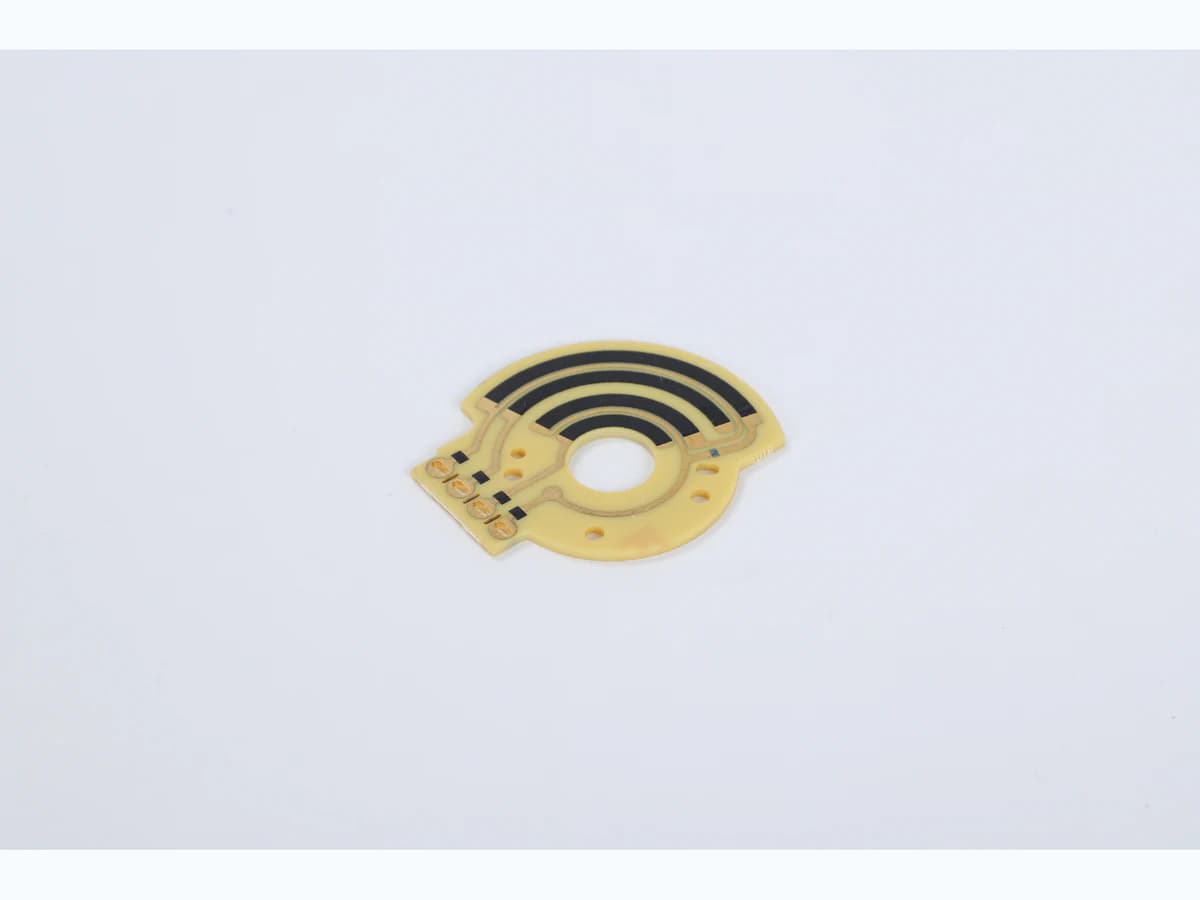
Treating the product photograph as proof of angle range, curve, accuracy, wear life, fluid compatibility, or automotive qualification.
Reference boundary
Public method sources
These sources support the engineering method and terminology used in this technical guide. They do not establish a ThickFilmPCB material list, capability limit, customer result, certification, or finished-product specification.
- 01SAE 2002-01-1074 — Design Guidelines for Automotive Fuel Level Sensors
Supports reviewing rotary potentiometer geometry, thick-film ink and contact materials, wear, noise, failure modes, and fluid chemistry as a coupled sensor system. Its examples do not establish ChipSimple design values or automotive qualification.
- 02SAE 921450 — Reliable Measurement of Fuel Level
Supports modeling float, arm, pivot, moving contact, resistor, housing, and indication as one measurement chain. It does not prescribe a universal rotary track law or product limit.
- 03NIST Technical Note 1297 — measurement uncertainty
Supports identifying mechanical-reference, electrical, repeatability, resolution, calibration, and model uncertainty in the measured transfer curve; it provides no sensor accuracy value.
Inputs for a practical review
Unknown values may be labelled unknown. The review should convert uncertainty into an explicit decision or validation task.
Send Drawings- 01
Target angle-output table or equation, datum, direction, active span, stops, dead bands, resolution, linearity/custom-law error, hysteresis, and monotonicity.
- 02
Excitation, source and load impedance, readout circuit, contact current, filtering, sampling, calibration, connector, and fault diagnostics.
- 03
Pivot, shaft, linkage, wiper radius, footprint, force, speed, runout, backlash, overtravel, housing, substrate location, and tolerance drawings.
- 04
Track, collector, conductor, terminal, protection, material, firing, trim, finish, cleaning, lubricant, and assembly requirements.
- 05
Temperature, humidity, media, particles, vibration, shock, storage, powered states, sweep directions, duty, and lifecycle profile.
- 06
Angle reference, fixture, sweep rate, data density, curve-fit and residual method, noise bandwidth, sampling, inspection, and acceptance rules.
- 07
Prototype variants, quantities, reference samples, traceability, drawing/software revision, substitutions, qualification ownership, and change triggers.