
On this page
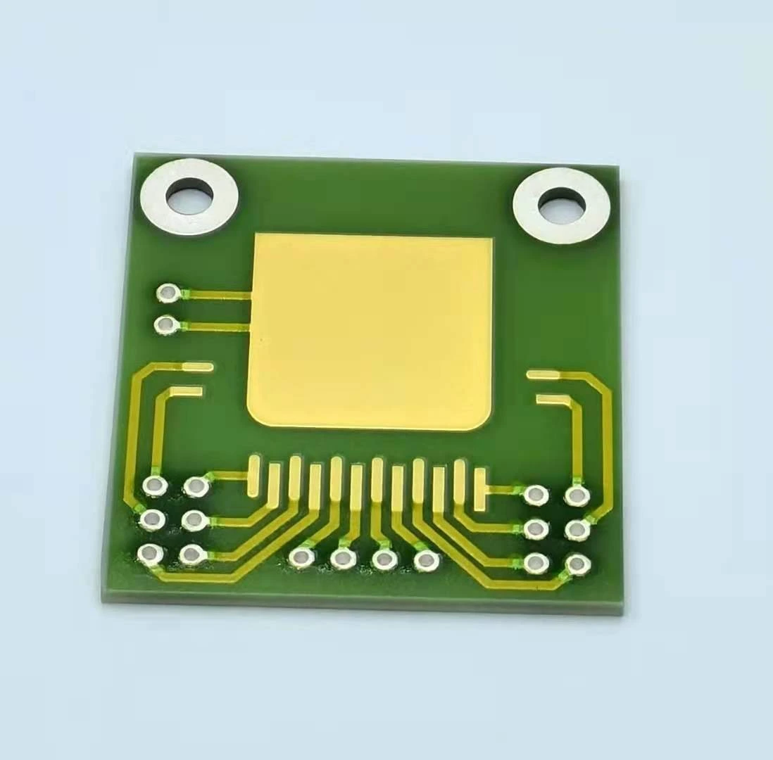
A clamped aluminum nitride circuit plate can move sideways while a fastener is tightened, even when the final axial load is acceptable. Friction under a rotating screw head or washer creates a moment that needs a return path. If the ceramic, its terminals or a small locating edge resist that moment, assembly can introduce damage before thermal operation begins. Draw the tightening moment separately from the normal clamping force.
System boundary
A specified AlN circuit and heat-sink stack retained by fasteners. The task is tightening-induced rotation during assembly. Final clamp preload, fracture strength and thermal performance remain separate mechanical and thermal qualification questions.
Integration interfaces
| Interface | Required input | Thick film role | Validation owner |
|---|---|---|---|
| Rotating fastener to bearing surface | Head, nut, washer, finish and location of the turning tool. | Remain outside the uncontrolled frictional reaction path. | Fastener and mechanical assembly owners define the bearing stack. |
| Heat sink to ceramic plate | Contact layer, locating arrangement and freedom for in-plane movement. | Maintain the reviewed thermal/electrical construction while retaining its intended position. | Module integrator verifies contact motion and ceramic support. |
| Fixture to assembly datum | Anti-rotation feature, reaction span and temporary support sequence. | Use stable locating features without loading a fragile printed region. | Tooling and process owners verify the reaction path during every fastening step. |
Integration risks
| Risk | Control or verification | Validation owner |
|---|---|---|
| A rotating washer drags the plate against one small stop. | Locate the rotating bearing interface and restrain an appropriate metal member rather than relying on the ceramic edge. | Mechanical design owner. |
| A lead prevents visible rotation while absorbing the moment. | Observe terminal movement and test assembly before external leads can act as restraints. | Interconnect and assembly owners. |
| Friction changes after reassembly and alters the load path. | Record surface state and compare the permitted reassembly sequence without assuming identical torque transfer. | Process qualification owner. |
System integration decisions
- Identify which rotating surface can drag the ceramic stack.
- Provide a reviewed torque-reaction path through the fixture or metal hardware.
- Observe rotation and interface movement during tightening, not just final torque.
Find the rotation that occurs before the final clamp state
Mark the component turned by the tool and every interface immediately below it. A screw head can rotate against a washer; a nut may rotate on the opposite side; a loose washer may turn with either surface. The path is not obvious from an exploded drawing, because friction decides which adjacent piece initially sticks and which slips.
Observe the intended sequence with temporary supports in place. Record whether the ceramic is already located before the fastener begins to load the stack. A plate that is free initially can rotate until it reaches a stop, then develop a concentrated reaction there. Its final position may look correct while the earlier contact event remains hidden.
Keep axial clamp force and tightening moment as different quantities
Clamp force acts mainly along the screw axis. A frictional moment acts about that axis. The torque indicated by the tool is distributed through thread and bearing interactions; it is not a direct measurement of the moment entering the ceramic, and it is not a unique measurement of preload.
Use a free-body sketch for each part of the stack. Draw axial forces, lateral forces and moments separately. Identify the structure that balances each one. If the drawing closes the moment through a soldered lead, an unsupported ceramic corner or uncertain surface friction, the tightening process depends on an electrical or brittle interface to perform an unintended mechanical job.
Estimate the reaction associated with a short restraint arm
A simple moment balance illustrates why a small edge stop can be demanding. Suppose an independently established frictional moment of 0.03 N·m reaches the retained member and one lateral reaction acts 6 mm from the axis. The corresponding force is 0.03/0.006 = 5 N. Moving the reaction to a reviewed metal fixture arm 30 mm away would require 1 N for the same moment.
These assumed numbers compare reaction geometry; they are not a fastener setting, ceramic allowable load or proof that the proposed fixture is safe. Multiple contact points require their stiffness and contact conditions to determine load sharing. The useful lesson is to inspect the actual lever arm rather than dismissing a small tightening moment as mechanically irrelevant.
F = M/r
- F: lateral reaction force in newtons for the stated single-reaction model.
- M: moment transmitted to the retained member, in N·m; not necessarily the tool torque.
- r: perpendicular distance from the rotation axis to the line of action of F, in metres.
Static moment balance with one effective reaction and no additional balancing couple. This does not calculate ceramic stress or allowable load.
Choose a reaction interface without creating a new point load
An anti-rotation feature should act on a member capable of carrying the reaction in the actual stack. Depending on the design, that may be a metal carrier, a keyed backing part or a fixture surface. Selecting such a feature requires its own clearance and load review; merely adding a pin beside the ceramic can replace distributed friction with a sharper contact.
Keep the ceramic's locating function distinct from torque restraint where possible. A datum contact can establish position without being suitable for the entire tightening moment. Do not modify an existing product outline, drill an extra hole or add a notch solely to make the assembly convenient without reopening the part design and its evidence.
Compare the fastening sequence with location-linked observations
Use temporary witness marks on removable tooling or recorded image landmarks that do not contaminate functional surfaces. Track angular movement of the retained member, lateral translation of the ceramic and displacement at its terminals. Record the order of fasteners and which member is held against rotation.
Do not choose an arbitrary universal cross-pattern or torque value. The validated sequence must match the actual support and hardware. A controlled comparison can change where torque reaction is taken while leaving the intended final clamp setting unchanged. If the plate moves less but a different local contact now carries the load, inspect that contact before accepting the change.
| Observation | Likely interface to inspect | Useful next observation |
|---|---|---|
| Plate turns with the washer | Bearing friction into the retained stack | Relative angle of washer, carrier and ceramic |
| Plate stops abruptly at one edge | Short-arm locating reaction | Contact mark and local movement at that stop |
| Ceramic appears still but leads move | Terminal restraint of the stack | Lead displacement before external cable restraint is fitted |
| Movement changes after remounting | Bearing or interface surface history | Same sequence with documented hardware and surface state |
| Opposite screws produce opposite shifts | Sequence-dependent moment balance | Position record after each individual fastening step |
Inspect the contact layer for drag, not only thickness
Sideways movement can shear or redistribute a thermal interface layer while the stack is being compressed. Record its initial placement and any displaced edge material after tightening. A final thickness measurement at one accessible edge does not establish that the same contact pattern remains beneath the whole heat source.
Compare a nonrotating reference assembly and the proposed tightening sequence using the same approved interface material and preparation. If a thermal change follows altered fastening, do not immediately attribute it to clamp pressure. Contact redistribution, trapped particles or shifted coverage can also change the heat path. Preserve photographs before disassembly changes the evidence.
Treat friction changes as engineering changes
Lubricating a screw, changing a washer finish or placing a slip layer in the stack can change both the tightening moment distribution and the resulting preload. Such changes may also affect cleanliness, electrical insulation or interface compatibility. They require approval for the actual materials and cannot be used as informal workshop remedies.
Document replacement hardware and permissible reuse. A surface that has already slid or been compressed may behave differently at the next assembly. If service includes removal, evaluate that state explicitly. The acceptance record should identify the physical stack and preparation, not only a torque-tool programme with a familiar name.
Hand off the torque path with the assembly drawing
Provide the turning-tool side, fastener stack, bearing surfaces, anti-rotation feature and reaction path on one annotated assembly view. Add the contact-layer position, temporary supports and final locating scheme. Distinguish the tool's assembly setting from any separately measured force or transmitted moment.
For a problem investigation, include the movement after each fastening step, hardware history, terminal position and before-and-after surface views. Final thermal checks and electrical continuity complement those observations but do not reconstruct an earlier edge impact. The desired outcome is a reproducible assembly sequence that keeps tightening reaction out of vulnerable ceramic and printed interfaces while preserving the independently qualified clamp condition.
Provide the AlN fastening and reaction path
Send the complete stack and the turning sequence so tightening-induced motion can be reviewed independently from final thermal contact.
- AlN circuit outline, thickness, holes, pads and actual support locations.
- Fastener, washer, carrier and heat-sink drawings with the side rotated by the assembly tool.
- Anti-rotation arrangement, temporary supports, interface material and fastening sequence.
- Measured movement, terminal displacement, surface marks and hardware reuse history; identify which force or torque quantities were actually measured.
The drawing-upload form loads as you reach this section.