
On this page
A battery test fixture can receive heat from its controlled heater, the cell under test, electrical contacts and the surrounding test environment. Those contributions change during an electrical test even when the fixture temperature setpoint stays constant. Integrating a printed heater therefore requires a clear boundary between the heating element, the cell holder, the electrical test system and the laboratory's environmental and protective equipment. The useful output is an interface specification that explains what is heated, what is measured and who validates the assembled test arrangement.
System boundary
The printed heater is a candidate heat-input component on the fixture side of a battery characterization system. Cell chemistry, permitted electrical and thermal test conditions, enclosure, ventilation, cooling, protective functions and test authorization remain with the cell and laboratory system owners. No energized-cell test procedure or battery-abuse protocol is specified here.
System integration decisions
- Keep heater electrical input separate from cell terminal power, cell-generated heat and terminal-contact losses.
- Define whether temperature refers to the fixture, cell surface, environment or another observable; none automatically represents cell internal temperature.
- Allocate independent protection and permission to operate to the battery-test system owner, not to the printed heater or its normal controller.
Do not interpret cell terminal power as heat generation
The heater converts its electrical input predominantly into heat, with some energy temporarily stored in its own temperature rise. A charging or discharging cell is different: terminal electrical power includes energy entering or leaving electrochemical storage. Multiplying cell voltage by current does not directly give cell-generated heat. Keep the heater supply channel and the cell electrical channel separately identified in both the schematic and the data record.
Contacts and interconnects can generate additional heat outside the cell body. Where a warm terminal appears, the review must distinguish cell behavior from losses at the fixture contact or current lead. A heater drawing cannot resolve that attribution. Record the physical locations of electrical connections and thermal observations so the laboratory can relate a temperature change to the relevant part of the system.
Choose a thermal control volume that matches the decision
A boundary drawn around the holder alone has different heat inputs from one drawn around the holder and cell together. Across the holder boundary, heat may enter from the heater and exchange with the cell, chamber air, mounting frame and cables. Across the combined boundary, heat generated within the cell becomes an internal contribution. Mixing these descriptions can count the same energy twice or omit a significant loss path.
A qualitative energy balance is useful before detailed simulation: stored thermal energy changes with heater input, internal heat generation and net heat exchanged with the environment. The signs must follow the selected boundary. This balance is a way to identify missing measurements and responsibilities, not a method for estimating an unknown cell's safe temperature or allowable test power.
Specify what happens when no additional heating is required
A resistive heater can add heat but cannot actively remove it. If the cell and its connections release more heat than the fixture can reject at the desired condition, reducing heater duty to zero may still leave temperature rising. That is an integration limit, not necessarily an error in heater resistance. The test arrangement needs a separately defined heat-rejection route and an operating boundary compatible with the authorized test.
Define the relationship among fixture heating, chamber conditioning and any dedicated cooling system. Two controllers acting on nearby sensors can work against one another if their responsibilities are unclear. The system integrator should identify the controlled object for each loop, the states in which it is enabled and how a loss of environmental control affects permission to continue. No universal temperature or power limit can be inferred from this allocation.
Treat the cell holder as a thermal and mechanical interface
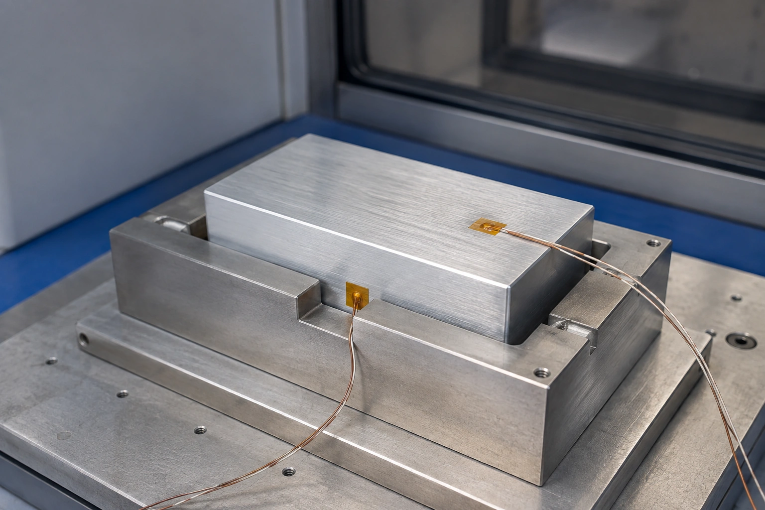
A heater mounted beneath a metal holder does not apply a known heat flux to the cell simply because its input power is known. Heat can spread into unused holder regions, fasteners and the supporting frame. The contact layer between holder and cell adds another resistance and may change when a specimen is replaced. Define the intended heat-transfer region separately from the electrical terminal contacts.
The cell supplier and fixture owner determine permissible restraint, contact pressure and accommodation of dimensional change. Do not increase clamping force merely to improve thermal contact. A ceramic heating element also needs a support arrangement compatible with its brittleness and terminal clearance. The drawing should show which component carries mechanical load and which surfaces transfer heat, including the changeable interfaces introduced during routine specimen replacement.
Name the temperature observable before specifying stability
Fixture temperature, exposed cell-surface temperature and chamber-air temperature are separate observations. A stable holder reading does not demonstrate a uniform cell surface, and an accessible surface measurement does not automatically establish internal temperature. State the location, attachment and reporting interval for each requirement. If an internal state is inferred from a model, its assumptions and validation belong to the test program.
Sensor placement can alter the interface it is intended to observe. A sensor inserted between the holder and cell may change local contact; leads can conduct heat away from a small measurement location. The metrology owner should address those effects together with calibration, response and spatial uncertainty. A precise instrument specification alone does not close uncertainty caused by an unobserved gradient.
Link thermal observations to the electrical test state
A temperature trace needs enough context to distinguish environmental drift, fixture heating and a change in the electrical test. Synchronize the permitted electrical-test state, heater command, measured heater input, cell electrical channels and temperature observations. Identify gaps, resets and changes of range rather than smoothing them into one apparently continuous record.
The useful synchronization tolerance depends on the event being interpreted. A slow equilibrium observation and a brief state transition do not need the same time resolution. Establish the required timing with the test engineer and preserve raw timestamps. A response that appears to precede a command may indicate separate clocks or buffered reporting rather than an unexpected thermal mechanism.
| Observation | Interface question | Decision owner |
|---|---|---|
| Holder temperature rises while heater input is zero | Is heat arriving from the cell, contacts or environment? | Battery test engineer and thermal integrator |
| A cell terminal is warmer than the adjacent holder | Does the electrical contact or current path contribute local loss? | Electrical fixture owner |
| Reported temperature changes after specimen replacement | Did contact, sensor attachment or participating mass change? | Fixture and metrology owners |
| Thermal response timing differs between data channels | Are timestamps, filtering and buffering aligned? | Acquisition and controls owner |
| One controller increases output while another removes heat | Are the control objects and enabled states compatible? | Environmental-system integrator |
Separate fixture characterization from battery test authorization
A non-energized, appropriately chosen thermal surrogate can help the fixture team examine contact repeatability, heater distribution and sensor installation. It cannot establish the thermal behavior, safety limits or electrical characteristics of a live cell. Its material, geometry and boundary conditions should be recorded so the result is not later presented as battery performance.
Validation involving energized cells belongs to the qualified laboratory under its approved procedures, equipment and cell-specific limits. The heater supplier contributes drawing, material-system and component verification information within the agreed scope. The test-system owner validates the combined electrical, environmental, acquisition and protective arrangement. A successful heater continuity check addresses the component, not the authorization or suitability of an assembled battery test system.
Keep normal regulation outside the claim of complete protection
Removing heater power does not remove stored cell energy or necessarily stop heat generated elsewhere in the system. The safety review must therefore extend beyond a heater overtemperature command. Assign responsibility for independent monitoring, power interruption, environmental equipment, communication loss and the laboratory's emergency arrangements without assuming that one controller implements all of them.
Record the approved response to a missing sensor, unavailable environmental service or lost state communication as a system requirement, not as an improvised operator action. Recovery and specimen disposition require defined authority as well. Any change to cell type, fixture contact, terminal assembly, heater, sensor attachment or controlling software should trigger review of the affected evidence before the revised arrangement is used.
Provide the fixture heating boundary
A heater review starts with the holder and its interfaces, while the laboratory retains cell-test conditions and operating authorization.
- Holder and heater drawings identifying cell contact, load-bearing surfaces, interface layers, terminals, fasteners and replaceable components.
- The permitted fixture thermal objective, external heat-rejection boundary and non-confidential load information approved by the test owner.
- Heater electrical supply, measurement references, sensor locations, attachment methods and synchronized channel requirements.
- Named mechanical, electrical, metrology and laboratory-safety owners, with the component verification records required for integration.
The drawing-upload form loads as you reach this section.