
Overview
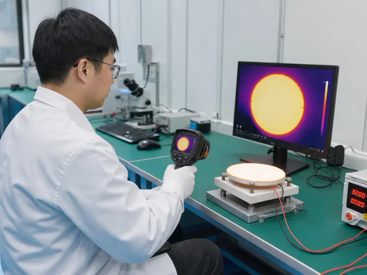
Precision thermal control in an instrument is a measurement-and-control problem bounded by the process, not a heater accuracy claim. The controlled object may be a cell, optical bench, detector, reagent zone, reference cavity, flow path, enclosure, or calibration fixture. Its temperature depends on heater placement, heat spreading, parasitic losses, ambient disturbances, airflow, nearby dissipation, sensor coupling, wiring, sampling, control dynamics, mechanical interfaces, insulation, warm-up, and operating sequence. This guide organizes those variables so an equipment team can specify what must be stable, where it is measured, over what time and environment, and with what uncertainty. It does not promise a temperature range, uniformity, stability, response time, power, calibration class, or safety compliance. Those results require the actual assembly, traceable measurements, a declared control strategy, and representative validation.
Engineering review matrix
Each row links a design variable to evidence that can support a drawing or release decision.
| Variable | Control question | Verification route |
|---|---|---|
| Controlled quantity | Is the requirement absolute temperature, point stability, spatial uniformity, repeatability, ramp tracking, or a process outcome linked to temperature? | Measure the actual controlled object with a documented reference method and report spatial and temporal results separately. |
| Sensor coupling | Where is the sensor relative to the controlled object, and what attachment, lag, self-heating, calibration, and wiring errors apply? | Calibrate the chain, characterize response and offsets in the assembly, and compare against additional mapped reference locations. |
| Heater distribution | How do trace density, zones, local losses, spreading layers, mounting, and edge conditions shape heat input? | Map temperatures and electrical input across representative tolerances and operating states; do not infer uniformity from artwork alone. |
| Control dynamics | What sampling, filtering, controller law, output resolution, saturation, ramp, transition, and settling definitions are used? | Record commands, measurements, output, limits, and state transitions during setpoint and disturbance tests using released software. |
| Disturbance envelope | Which ambient ramps, airflow, fluid flow, door states, adjacent loads, supply changes, orientation, and operating sequences matter? | Execute a matrix covering declared normal and degraded conditions while holding other inputs traceable. |
| Measurement uncertainty | Which calibration, readout, gradient, position, temporal, repeatability, and fixture components contribute to the reported result? | Maintain an uncertainty budget linked to reference identity, calibration interval, setup, raw data, calculation, and acceptance decision. |
| Fault behavior | What happens after sensor open, short, drift, detachment, stale data, controller reset, stuck output, supply fault, or airflow loss? | Inject permitted faults under the equipment owner's safety plan and verify detection, output limitation, safe state, warning, and recovery. |
Precision thermal-control definition sequence
The order makes assumptions and ownership visible before a result is promoted to a requirement.
- 01
Define the measurand and controlled object
Name the physical quantity that matters to instrument performance and distinguish it from the controller display. Identify the sample, fluid, optical element, detector, reference, enclosure air, or surface whose temperature must be known. State spatial locations, time window, operating phase, allowed gradients, and whether the requirement concerns absolute temperature, stability, repeatability, tracking, or uniformity.
- 02
Map heat sources and disturbances
Document the printed heater, electronics dissipation, lamps, motors, pumps, fluid flow, conduction through mounts and cables, radiation, enclosure exchange, fan states, door opening, ambient ramp, condensation risk, and neighboring zones. Convert each foreseeable condition into a defined test case rather than a generic ambient statement.
- 03
Place sensor and heater as a pair
Show heater distribution, sensor location, attachment, contact area, thermal path, response, self-heating, lead conduction, multiplexing, calibration, and service replacement. Evaluate the physical distance and lag between the measurement point and the protected or controlled object. A precise sensor cannot remove an unobserved gradient.
- 04
Specify control behavior
Provide sampling, filtering, setpoint ramps, feed-forward terms, actuator resolution, output limits, control period, anti-windup, mode transitions, warm-up, overshoot rule, settling definition, standby, fault detection, and safe state. Separate closed-loop performance from open-loop heater resistance and power tolerances.
- 05
Build an uncertainty and variation budget
Include reference calibration, sensor interpolation, readout error, noise, self-heating, attachment, position, gradient, temporal variation, fixture loading, ambient measurement, repeatability, manufacturing tolerance, and software processing. Express which terms are corrected, bounded, sampled, or left as validation uncertainty.
- 06
Validate the complete thermal zone
Test the intended object, heater, spreader, insulation, mounts, sensors, electronics, controller, enclosure, airflow or fluid, cables, firmware, and operating sequence. Retain synchronized raw temperature, power, state, and disturbance data. Release only the tested configuration and establish change triggers for geometry, material, sensor, control, and enclosure revisions.
Failure controls
These are review prompts, not evidence that every risk applies or that every test is available.
- A
A stable controller display can coexist with an uncontrolled sample temperature when the sensor is thermally remote or poorly attached.
- B
Quoting sensor accuracy as system accuracy ignores gradients, calibration chain, electronics, self-heating, mounting, and time response.
- C
A tune developed with an empty fixture can overshoot or oscillate when the process mass, fluid, cover, airflow, or adjacent load changes.
- D
Averaged data can hide cyclic ripple, local hotspots, state-transition excursions, or short sensor dropouts that affect the process.
- E
One environmental point does not establish performance over ambient ramps, fan variation, supply tolerance, orientation, or enclosure changes.
- F
If the thermal function is safety-related, its integrity and fault response require the applicable equipment and functional-safety process; this page cannot allocate it.
Reference boundary
Public method sources
These sources support the engineering method and terminology used in this technical guide. They do not establish a ThickFilmPCB material list, capability limit, customer result, certification, or finished-product specification.
- 01NIST Guide to Secondary Thermometry — Industrial PRTs
Describes comparison calibration, interpolation, temperature-control media, and uncertainty considerations for industrial platinum resistance thermometers. It supports measurement planning but does not specify this instrument or validate a heater assembly.
- 02IEC 61010-1:2010+A1:2016 — Measurement Equipment Safety
Provides general safety requirements for electrical measurement, control, and laboratory equipment. The equipment owner must select applicable particular standards and complete qualified assessment; no compliance is implied here.
Inputs for a practical review
Unknown values may be labelled unknown. The review should convert uncertainty into an explicit decision or validation task.
Send Drawings- 01
Instrument and thermal-zone drawing showing controlled object, heater, spreader, insulation, mounts, sensors, airflow or fluid, enclosure, and nearby heat sources
- 02
Temperature objective with locations, setpoints, absolute accuracy, stability, uniformity, repeatability, ramps, settling, duty cycle, and reporting interval
- 03
Sensor type, attachment, calibration, readout, wiring, excitation, filtering, sampling, replacement, and uncertainty requirements
- 04
Heater voltage, resistance or power control, zones, drive topology, output resolution, limits, switching, grounding, and insulation boundary
- 05
Controller law, mode transitions, warm-up, standby, faults, diagnostics, alarms, safe state, software revision, and data logging
- 06
Ambient, airflow, fluid, load, orientation, humidity, condensation, vibration, cleaning, storage, and adjacent-dissipation conditions
- 07
Prototype quantity, reference instruments, mapping fixture, test matrix, uncertainty format, acceptance authority, and applicable standards