
On this page
A mounting-hole center can satisfy the drawing while the installed washer reaches a nearby conductor. Clearance in the washer hole allows translation, and a noncircular washer changes its outer reach as it rotates. Inspect the complete conductive envelope at the permitted assembly positions. The resulting distance is an input to the electrical insulation review, not a voltage rating and not proof that any particular spacing is safe.
System boundary
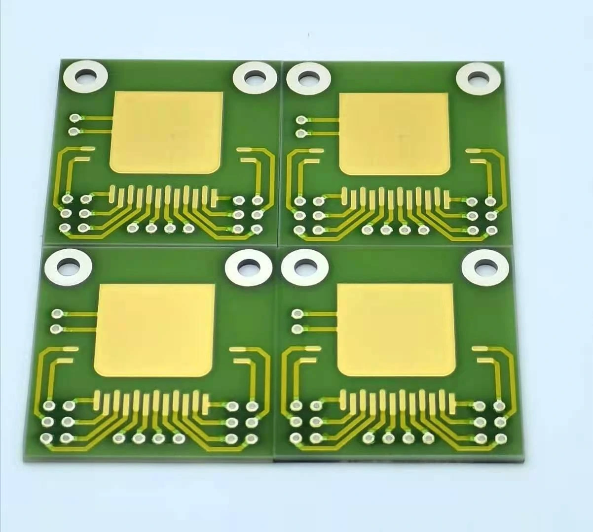
Conductive fastener hardware near a ceramic circuit's energized regions. The review determines geometric approach and inspection coordinates; applicable insulation requirements and safe electrical testing remain with the qualified system owner.
Integration interfaces
| Interface | Required input | Thick film role | Validation owner |
|---|---|---|---|
| Washer hole to fastener shank | Hole/shank dimensions and permitted lateral movement. | Locate the mounting feature relative to finished printed boundaries. | Mechanical designer defines the hardware position envelope. |
| Washer outer edge to conductor | Outer profile, rotation, burr condition and conductor location. | Maintain the reviewed conductor keep-out in finished geometry. | Circuit and mechanical owners reconcile relative dimensions. |
| Hardware potential to insulation system | Intentional ground connection or other electrical state and environment. | Keep functional return and insulation boundaries explicit. | System insulation owner determines electrical acceptance. |
Integration risks
| Risk | Control or verification | Validation owner |
|---|---|---|
| Nominally centered hardware moves toward a live trace. | Use the permitted eccentric position in the envelope. | Mechanical owner. |
| A rotating corner approaches farther than the nominal side. | Overlay every permitted angle for noncircular hardware. | Hardware drawing owner. |
| A top-view gap is reported as complete insulation approval. | Review air, surface and solid paths independently under the applicable requirements. | Qualified system owner. |
System integration decisions
- Use the outer conductive hardware boundary, not the ceramic hole diameter, as the moving obstruction.
- Include washer-to-shank freedom and fastener position only once in the relative geometry budget.
- Check electrical paths in three dimensions after the mechanical envelope is defined.
Inventory every conductive item at the mounting point
List the screw head, flat or spring washer, nut, sleeve, standoff and any retained clip. Their outer dimensions and heights need not match. The closest metal may be under the ceramic or above a nearby component rather than the item most visible in the top photograph.
Identify the electrical state of the hardware. It may be deliberately bonded to chassis, connected to a functional return or isolated from both. Do not infer that state from metal-to-metal appearance or from the color of a coating. The existing ground-return review addresses the electrical connection; this page defines the geometric region the hardware can occupy.
Calculate the washer's lateral freedom
For a circular washer hole on a circular shank, the maximum ideal center offset is half the hole diameter minus half the shank diameter. Use maximum hole and minimum shank dimensions for the corresponding worst-position screen. Additional movement of the shank inside the ceramic hole is a separate relative term if it has not already been included in the fastener-location allowance.
A washer is not necessarily centered when tightened. Friction, gravity, tool contact or assembly orientation can leave it near one side of the available clearance. A drawing that relies on centering needs a physical locating feature or a controlled condition that actually establishes it. An instruction to center by eye should not be treated as a precise geometric constraint.
Work through a circular washer example
Assume a washer outer radius of 3.0 mm, maximum hole diameter of 3.6 mm and minimum shank diameter of 3.0 mm. Its center can move 0.30 mm relative to the shank. If the fastener axis has a further 0.15 mm permitted displacement toward a conductor, the outer reach from the nominal axis becomes 3.45 mm.
Suppose the nearest finished conductor edge is nominally 4.20 mm from that axis and has a separate 0.10 mm allowance toward the hardware. The remaining one-direction geometric gap is 4.20 − 0.10 − 3.45 = 0.65 mm. These assumed dimensions explain the budget only. They are not recommended hardware sizes or acceptable electrical separation.
e_w = (D_h,max − D_s,min)/2; g = d_edge − e_print − r_w,max − e_w − e_axis
- e_w: maximum washer-center offset relative to the shank, in mm.
- D_h,max and D_s,min: washer-hole maximum diameter and shank minimum diameter, in mm.
- g: screened geometric gap toward the evaluated conductor, in mm.
- d_edge: nominal axis-to-conductor-edge distance, in mm.
- e_print and e_axis: nonduplicated conductor and axis position allowances toward each other, in mm.
- r_w,max: maximum circular washer outer radius, in mm.
Planar circular hardware and one adverse direction. Actual three-dimensional paths, shape defects, rotation of noncircular parts and electrical requirements require separate evaluation.
Treat noncircular and tilted hardware separately
For a square, tabbed or otherwise noncircular washer, rotation changes the outer reach. Use the union of all permitted positions and angles, or restrict angle through an actual keyed feature. A side dimension is not the maximum corner reach. A circular washer does not gain outer radius by rotating, so adding an arbitrary rotation allowance to it would misstate the mechanism.
Include height and possible tilt where an adjacent conductor or terminal is not coplanar. A raised washer edge may approach a bent lead above the ceramic while maintaining a comfortable surface gap. Review the assembled section and installation path. A flat top-view circle cannot describe every conductive obstruction around the mounting point.
Measure the finished conductor and hardware boundaries
Use the processed conductor edge and actual hardware profile. The printed artwork may not represent fired spread, while a washer drawing may exclude burrs or damage that appear on a supplied part. The appropriate hardware acceptance controls should prevent unreviewed protrusions; do not hide them inside an unexplained electrical margin.
View the region before it becomes obscured, then confirm the assembled position where accessible. Record the hardware identity and orientation. Replacing a washer with a larger convenient part during service changes the envelope even if the screw thread remains the same. Keep approved alternatives tied to their complete geometry, not only their nominal bolt size.
Carry the envelope into the insulation review
Air clearance and a path along an insulating surface are different geometric routes. A washer touching an insulating sleeve can introduce another surface interface; a screw below the ceramic may create a shorter route than the visible top edge. The responsible insulation review must evaluate the complete assembly and applicable operating conditions.
The presence of green glass overglaze does not automatically establish a qualified protective insulation system. Do not infer an allowable voltage from the calculated gap, a photograph or a generic table. Working and transient voltage, environment, material system and end-product requirements determine the acceptance basis. The mechanical envelope tells that review where the conductive object can actually be.
Choose the change that addresses the controlling movement
If eccentric movement controls the gap, compare a positively located hardware arrangement rather than only moving the nominal center. If a rotating corner controls it, constrain orientation or review a different approved profile. If the underside standoff is closer than the washer, changing the top washer will not remove the limiting route.
Check mechanical load distribution before substituting smaller hardware. A washer chosen for electrical clearance still has to perform its structural function without concentrating unacceptable load on the ceramic. Electrical and mechanical improvements must be evaluated together, not traded through an informal part substitution.
| Controlling feature | Relevant change | Check retained |
|---|---|---|
| Lateral washer freedom | Locate washer or reduce reviewed clearance | Assembly tolerance and bearing function |
| Noncircular corner rotation | Key orientation or revise approved profile | All permitted angles |
| Underside standoff approach | Revise lower hardware boundary | Three-dimensional insulation paths |
| Finished conductor spread | Review actual print-to-hole relation | Processed geometry rather than artwork only |
| Burr or damaged edge | Apply hardware quality disposition | Do not treat damage as normal geometry |
Issue the hardware envelope with the circuit drawing
Provide the fastener stack, permitted alternatives, movement limits, outer envelopes and nearest conductor coordinates. Distinguish measured dimensions from allowances, and state which terms share a datum so they are not double counted. Include the required inspection views and the electrical state assigned to the hardware.
Recalculate after washer, standoff, hole, conductor, sleeve or assembly-orientation changes. The deliverable is a reproducible geometric separation for the actual mounting arrangement, followed by the appropriate mechanical and insulation decisions. This is more useful than a mounting-hole keep-out that ignores the metal surrounding the hole.
Send the complete conductive mounting stack
Provide hardware movement and finished conductor positions so the installed envelope can be reviewed accurately.
- Screw, washer, nut, sleeve and standoff dimensions including approved alternatives.
- Hole/shank fits, axis location, permitted rotation and assembled heights.
- Finished conductor boundaries, layer/face identity and relevant registration allowances.
- Hardware electrical connection, insulation requirements and inspection access.
The drawing-upload form loads as you reach this section.