
On this page
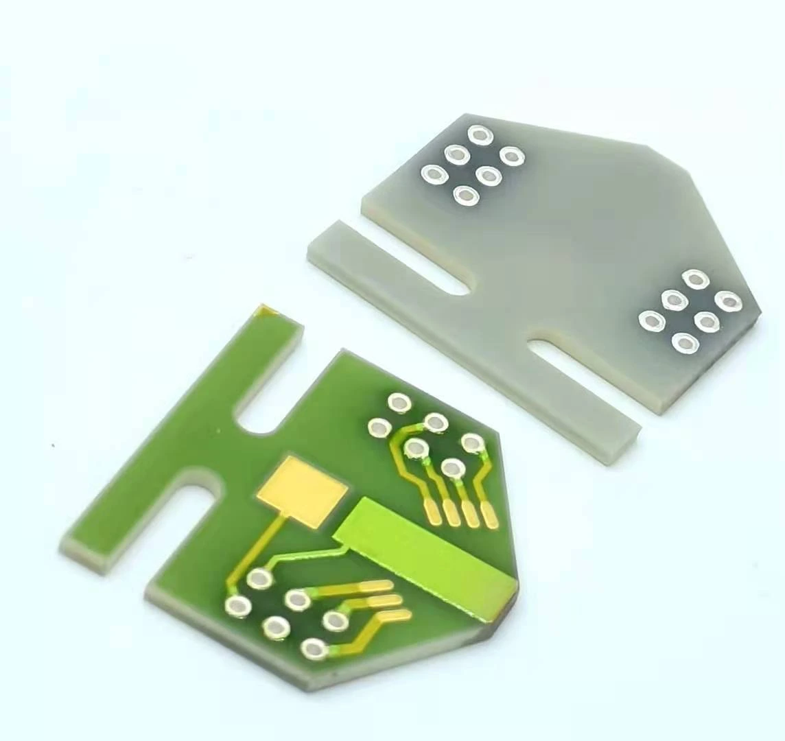
An isolation slot may be clean when the ceramic circuit is inspected and still collect a wire clipping or fastener fragment when the enclosure is assembled. Increasing the slot length does not prevent that transfer. Review the operations performed above and beside the circuit, where loose material can travel, and whether the final pocket can be inspected. The practical output is a source-to-slot map with a last-clean inspection point that occurs after the relevant debris-generating work.
System boundary
A ceramic PCB with an existing isolation opening mounted inside an enclosure containing leads, fasteners or other potentially particle-generating operations. This review controls assembly access and contamination paths; the insulation design and safety requirements remain separate.
Integration interfaces
| Interface | Required input | Thick film role | Validation owner |
|---|---|---|---|
| Assembly operation to loose particle | Lead cutting, thread engagement, trimming and handling sequence. | Identify the exposed isolation and conductor regions that must remain protected. | Assembly process owner identifies actual particle sources. |
| Enclosure pocket to ceramic slot | Orientation, ledges, airflow and clearance below the opening. | Preserve the intended insulation boundary in the installed state. | Mechanical integrator reviews transfer and collection paths. |
| Inspection view to final closure | Visible surfaces, illumination and the last accessible assembly state. | Provide identifiable slot coordinates and nearby conductor boundaries. | Quality owner defines observations and disposition criteria. |
Integration risks
| Risk | Control or verification | Validation owner |
|---|---|---|
| A clean ceramic is contaminated during subsequent lead cutting. | Move or contain the cutting operation and verify the circuit afterward. | Assembly owner. |
| A pocket releases hidden debris when the module is rotated. | Evaluate the real orientation sequence with appropriate collection controls. | Mechanical and quality owners. |
| Cleaning moves particles into an inaccessible region. | Inspect the receiving regions as well as the original dirty surface. | Cleaning-process owner. |
System integration decisions
- Separate contamination already on the ceramic from debris introduced by later enclosure work.
- Follow the particle path through assembly orientations, not only the final installed orientation.
- Make the last particle-generating step and the last effective inspection explicit.
Start the map at the last known clean state
Identify the state in which both faces and the slot were last observed. Record the assembly revision, orientation and features already installed. This is the comparison point for later contamination, not proof that the completed module remains clean. A receipt photograph taken before leads and hardware are added cannot represent the final cavity.
List every operation after that point that can create, release or transfer loose matter. Examples to investigate include lead trimming, fastener engagement, removal of temporary ties and handling of carriers. Do not assume each operation produces conductive material; observe representative work and identify what is actually present. Material identity and source timing should be recorded separately.
Follow the particle through changing orientations
Draw the circuit, slot, enclosure ledges and likely source positions in the assembly orientation. Repeat the drawing for the orientation used during transport, closure and service. A fragment resting harmlessly on a ledge during one step may fall toward the ceramic when the housing is turned. The final orientation alone can conceal that path.
Include transfer by contact with gloves, tools or removable covers when it is plausible for the actual operation. Airflow can also move loose particles, but do not assume blowing a region clear removes them from the assembly. Identify where the displaced material goes. A useful path map ends at a collection or removal location, not at an arrow pointing away from the visible surface.
Choose the change that removes the source-to-slot path
Consider an illustrative module assembled with the ceramic installed first, internal leads cut second and the lid fitted third. The slot was inspected before lead cutting. If cut fragments are found beneath the slot after closure, repeating only the incoming ceramic inspection cannot address the source. The candidate change is to complete lead preparation away from the exposed circuit, or contain the operation and inspect all receiving regions afterward.
Compare that with a second sequence in which debris exists before the ceramic enters the housing. Here the useful action may be cleaning and checking the enclosure pocket before insertion. The same final symptom calls for a different intervention because the first appearance is different. The table makes that decision explicit without inventing a general cleanliness limit.
| First observed state | Possible transfer path | Focused action | Confirmation |
|---|---|---|---|
| Before ceramic insertion | Contaminated enclosure pocket | Clean and inspect the empty housing | Retain the pocket view before insertion |
| After lead trimming | Fragment falls from cutting location | Prepare away from the circuit or contain the cut | Check slot and receiving surfaces afterward |
| After hardware installation | Loose matter follows thread work | Review hardware and operation location | Compare before/after the individual operation |
| After housing rotation | A ledge releases stored debris | Remove the trap or control its cleaning access | Observe the actual orientation transition |
| After cleaning | Material moved to a hidden recess | Revise removal and collection path | Check both source and receiving regions |
Preserve a suspect particle before changing its location
Record the particle position relative to both conductor edges, the slot and nearby hardware. Include scale, viewing direction and the assembly state. A collected fragment without its original position cannot show whether it crossed the electrical boundary, sat on insulating material or arrived during teardown.
Use an appropriate collection method that does not contaminate or damage the relevant surfaces, and retain a blank from the collection medium when analysis is required. A metallic appearance is not enough to identify a fragment's composition. Equally, identifying conductive material does not prove it bridged two conductors. Geometry, material and electrical observations answer separate parts of the investigation.
Do not use cleaning to erase an unresolved fault
If a returned module has an intermittent leakage or short-circuit symptom, preserve its initial state before applying airflow, liquid or mechanical cleaning. Moving the fragment can eliminate the symptom while removing the evidence needed to prevent recurrence. Record electrical observations only through a procedure appropriate to the circuit's energy and insulation requirements.
For a proposed production cleaning method, verify compatibility with the actual fired films, components, polymers and wire bonds. A method effective on an empty ceramic substrate may be unsuitable for an assembled hybrid. Define particle removal and collection, drying where applicable, and checks for redistributed matter. A brighter appearance is not a substitute for that evaluation.
Place the final accessible inspection after the relevant work
The final inspection point should follow the last operation capable of introducing the identified debris, while the affected regions remain visible. If those conditions cannot both be met, the assembly route contains an access conflict. Resolve it by changing order, containment or access, rather than adding a sign-off to a state that cannot be examined.
Keep later operations visible in the record. Installing the last lid screw or removing a temporary cover can introduce a new source after an otherwise effective inspection. The review should therefore follow the complete route through closure. The inspection plan describes the actual module and agreed criteria; it is not borrowed from another manufacturer's qualification programme.
Hand off the source map and the insulation boundary together
Provide the assembly sequence, orientation changes, source observations, receiving pockets and inspection views. Mark the ceramic conductor boundaries and slot coordinates so findings can be tied to the electrical layout. Identify who owns the insulation design, enclosure process and cleaning method, and which observations require escalation before the module is powered.
Reevaluate the map when a lead length, fastener, housing pocket, cover or cleaning method changes. A minor mechanical change can introduce a new transfer path without altering the ceramic artwork. The result is a practical prevention and inspection arrangement for the declared assembly, while electrical spacing, environmental qualification and safe testing remain governed by their own requirements.
Send the slot and enclosure assembly sequence
Provide the operations and hidden receiving regions around the ceramic PCB so contamination prevention can be addressed at its source.
- Both-face circuit drawings, slot locations, nearby conductors and enclosure pocket geometry.
- Lead preparation, hardware installation, cleaning, orientation changes and closure order.
- Before-and-after particle photographs tied to the first observed operation and position.
- Permitted cleaning methods, inspection access and the responsible insulation and safety requirements.
The drawing-upload form loads as you reach this section.