
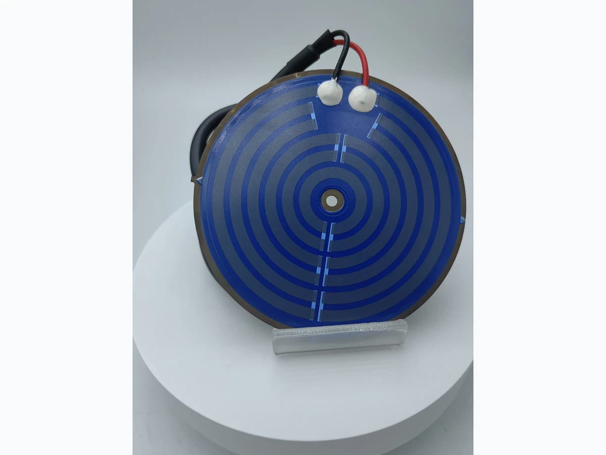
Overview
A coffee or water-heating system is more than a printed heating track. Its behavior depends on the vessel or flow path, water volume and chemistry, thermal interfaces, pump or fill sequence, steam and pressure management, temperature sensing, power switching, normal controls, independent protection, insulation, earthing, user-accessible surfaces, cleaning, scale accumulation, and foreseeable abnormal states. This guide helps an appliance developer turn those system conditions into reviewable heater inputs and assembly tests. It does not assign a universal wattage, heat-up time, dry-run limit, food-contact status, lifetime, or safety certification. IEC 60335-2-15 is cited as one scope example for household and similar liquid-heating appliances; commercial vending, instantaneous-water, medical, industrial, vehicle, and pressure applications may require different or additional standards.
Failure controls
These are review prompts, not evidence that every risk applies or that every test is available.
- A
A heater that appears stable in free air can develop very different gradients after bonding, clamping, scale accumulation, partial wetting, or blocked flow.
- B
Treating normal temperature regulation as independent protection can leave one sensor, switch, power device, or software path as a common-cause failure.
- C
A single water sample does not represent geography, season, treatment, cleaning chemicals, or deposit behavior, so the conditioning basis must be documented.
- D
Using a household coffee-maker standard without confirming commercial, vending, instantaneous, pressure, medical, or industrial scope can misdirect the safety plan.
- E
The visible heater pattern does not establish food-contact status, water-contact compliance, wattage, voltage, maximum temperature, or assembly lifetime.
- F
Changing vessel material, interface thickness, sensor location, pump timing, firmware, or protection device can invalidate earlier thermal and abnormal-test results.
Liquid-heating system integration sequence
The order makes assumptions and ownership visible before a result is promoted to a requirement.
- 01
Classify the end equipment
State whether the product is a household coffee maker, professional food-service appliance, vending machine, kettle, instantaneous water heater, laboratory device, or industrial system. Record jurisdiction, rated supply, user, installation, pressure boundary, accessible surfaces, cleaning method, and applicable product standards. A familiar product name is not a substitute for scope classification.
- 02
Describe the fluid and heat path
Map inlet temperature, volume or flow, water chemistry, dissolved minerals, additives, cleaning agents, stagnation, boiling or steam state, pressure, vessel material, heater contact, thermal interface, insulation, and heat losses. Identify wetted parts separately from electrically active layers and document who owns food-contact or water-contact review.
- 03
Define every operating state
List fill, prime, warm-up, brew or dispense, hold, reheat, purge, descale, cleaning, standby, power interruption, restart, and end-of-life service states. For each state, specify energization logic, expected fluid condition, flow, temperature targets, maximum allowed exposure, and permitted transitions.
- 04
Separate regulation from protection
Show the normal temperature controller, sensor, software, switching device, independent limiter or cutout, fuse or one-shot device, and resulting safe state. Document shared components and common-cause paths. A software setpoint or a nearby sensor is not automatically an independent dry-run protection measure.
- 05
Validate representative assemblies
Test the actual heater, vessel or flow body, interfaces, wiring, insulation, controller, sensors, protection devices, mounting, and enclosure. Control supply, inlet water, flow, scale or deposit method, orientation, ambient, and measurement locations. Include approved abnormal cases without extrapolating from an open-air heater sample.
- 06
Link release to manufacturing controls
Tie the accepted assembly to drawings, heater resistance, interface flatness, clamp or bond process, sensor position, wiring, insulation, leakage checks, software revision, protection-device identity, and end-of-line tests. Record deviations and retest rules so a later change in vessel, fluid path, or controller does not silently invalidate the evidence.
Engineering review matrix
Each row links a design variable to evidence that can support a drawing or release decision.
| Variable | Control question | Verification route |
|---|---|---|
| Fluid duty | What fluid, inlet range, dose or flow, pressure, phase change, chemistry, scale potential, and cleaning exposure define service? | Run controlled normal and aged or deposit-conditioned tests using a documented fluid and cleaning basis selected by the appliance owner. |
| Heater interface | How are heater layers connected thermally and mechanically to the vessel or flow body, and what gaps, bonds, clamps, coatings, and tolerances matter? | Inspect the built interface and correlate local temperatures and heat-up behavior across allowed assembly variation. |
| Control sensor | Where is temperature sensed, what time constant and calibration apply, and how does flow or trapped air change the reading? | Compare the control reading with calibrated measurements at critical fluid, vessel, heater, and accessible-surface locations. |
| Dry-run state | Which loss-of-fluid, failed-fill, blocked-flow, air-lock, empty-vessel, or delayed-sensor cases can energize the heater? | Execute only approved abnormal tests with controlled energy, containment, instrumentation, and an appliance-level safety owner. |
| Scale and deposits | What water basis, deposit method, location, thickness or mass indicator, and cleaning cycle represent foreseeable service? | Use a repeatable conditioning method and compare temperature, control response, protection action, leakage, and post-test integrity. |
| Electrical protection | What supply, switching, earthing, insulation, creepage, clearance, leakage, moisture, and accessible-part requirements apply? | A qualified safety laboratory applies the selected appliance standard to the complete construction and approved abnormal conditions. |
| User and service exposure | Which surfaces, steam paths, liquids, connectors, cleaning actions, and service steps can expose a user or technician? | Review instructions and foreseeable misuse, then verify temperature, spill, ingress, discharge, and service states under the applicable product scope. |
Reference boundary
Public method sources
These sources support the engineering method and terminology used in this technical guide. They do not establish a ThickFilmPCB material list, capability limit, customer result, certification, or finished-product specification.
- 01IEC 60335-2-15:2024 — Appliances for Heating Liquids
Covers specified household and similar liquid-heating appliances, including coffee makers, and identifies exclusions and updated hazards such as spills and surface temperatures. It is a scope reference, not evidence of product compliance.
- 02IEC 60335-1:2020 — Household Appliance General Safety
Provides the general safety framework used with applicable IEC 60335 part-2 standards. The equipment owner and qualified laboratory must select the correct edition and national deviations; this citation grants no certification.
Inputs for a practical review
Unknown values may be labelled unknown. The review should convert uncertainty into an explicit decision or validation task.
Send Drawings- 01
End-equipment classification, jurisdictions, applicable standards, rated supply, user, installation, and normal or professional use
- 02
Fluid path drawing with vessel, volume or flow, pressure, steam route, wetted materials, inlet range, water chemistry, and cleaning agents
- 03
Heater construction and mounting drawing with resistance target, power states, interface, flatness, bond or clamp, insulation, terminals, and wiring
- 04
Operating-state sequence including fill, prime, heat, dispense, hold, descale, standby, restart, and foreseeable abnormal states
- 05
Control and protection schematic showing sensors, switching, software, diagnostics, independent limiter, fuse, and safe-state behavior
- 06
Temperature, heat-up, accessible-surface, leakage, insulation, dry-run, blocked-flow, scale, cycling, and acceptance requirements
- 07
Prototype quantity, representative vessel and controls, test ownership, records, change-control plan, and evidence-release authority